I have created a process that simulates the horizontal wellbore creation processes for a client. However, I am stumped on, what seems to be a rather "newbie" process of flipping 180 degrees a select set of features. Let me illustrate further:


In the example below the user selects a township to create the horizontal wellbores. The workbench tiles the township into 6 sections by default. They next pick a direction (ie East/West or North/South.) Next they choose a starting location for the Surface Hole (N, S, E, or W.) Lastly they choose how many wells to place in each section.


The result is this of a North/South orientation with the surface hole in the south and 6 horizontal wellbores placed in the sections. So far, no issues this is version 1 where they all go in the same direction.
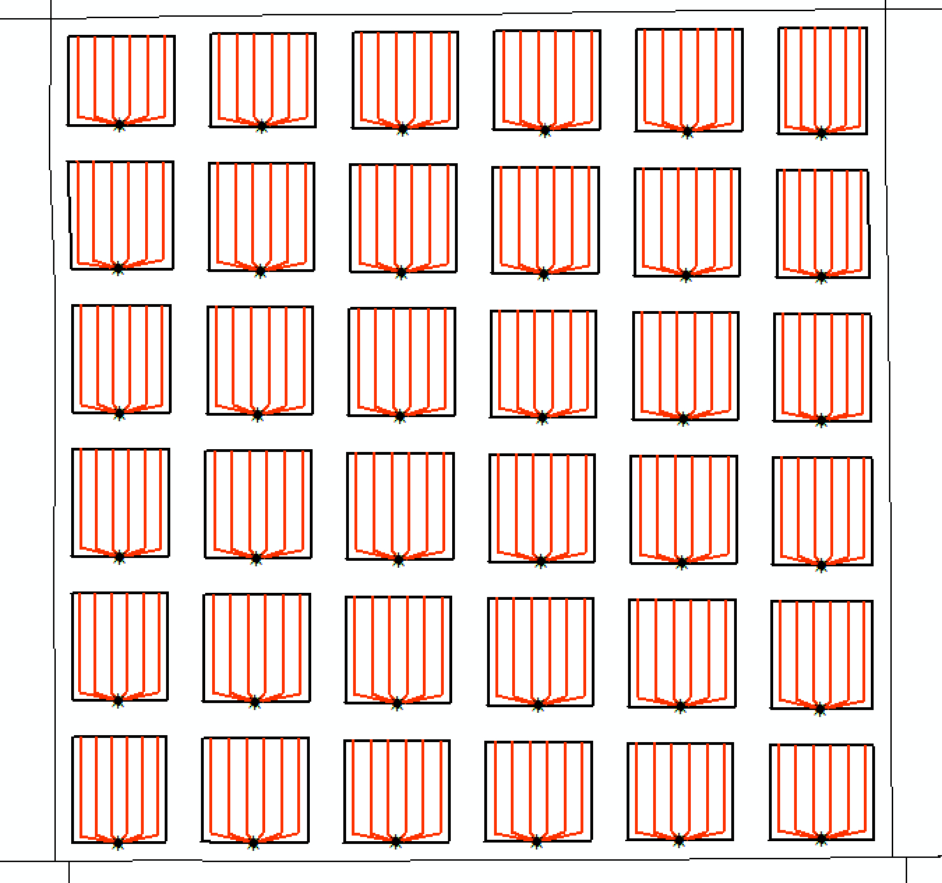


However, the client also wants the option of creating a "pad well" style drilling progam. In this case alternating rows would be flipped or reversed. Normally I am able to figure this out no problem as during the tiling process I can easily filter out row vs column and place a TestFilter.


So far I am unable to simply "flip" the features. I've tried 'Orientor' and 'Rotator' with results varying as much as doing nothing at all to rotating around random locations. In the instance of Rotator I even extracted the X, Y coordinates of each section and used that as the roation point but again the rotation was all over the place. Not sure whats happening here.


In the example below I've mocked up an example of an ideal scenario where the "odd" rows are flipped.
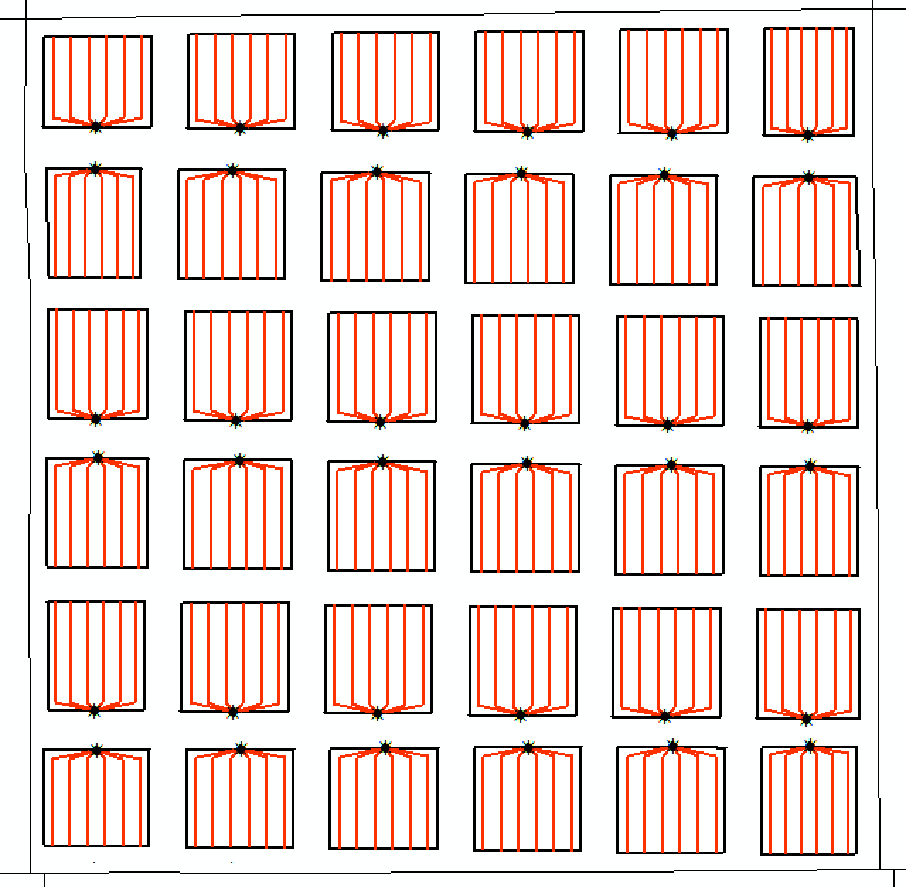


Further advanced functionality/exposed parameters would allow the client to choose Odd or Even rows, etc... I've alrady built the logic and can get the selection of the correct row or column but simply can't flip the features.


Any help or assistance would be appreciated.


Regards,


Matthew Brucker
Hi Matthew,


A unit seems to consist of multiple geometries - a rectangle, red lines and something like asterisk. If they have common identifier of belonging unit (e.g. UNIT_ID):


Transform them into collection type features using the Aggregator (Group By: UNIT_ID).


Extract bounds (xmin, xmax, ymin, ymax) of each collection feature with the BoundsExtractor.


Use the Rotator to rotate odd (or even) row features around their center coordinate (x = (xmin+xmax)*0.5, y = (ymin+ymax)*0.5).


If necessary, decompose the collection features to restore original geometry types (Deaggregator).


If they don't have common ID, consider create rectangle ID and give it to other associated features using the SpatialFilter.


Hope this helpd.


Takashi
Hi,


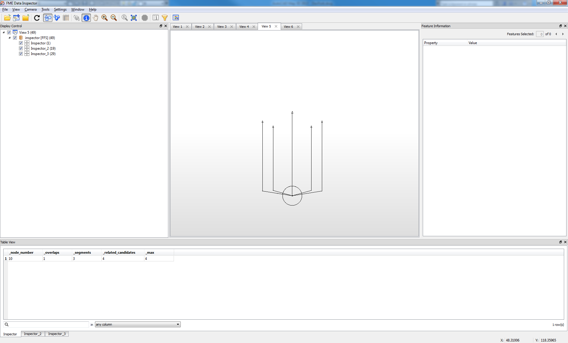
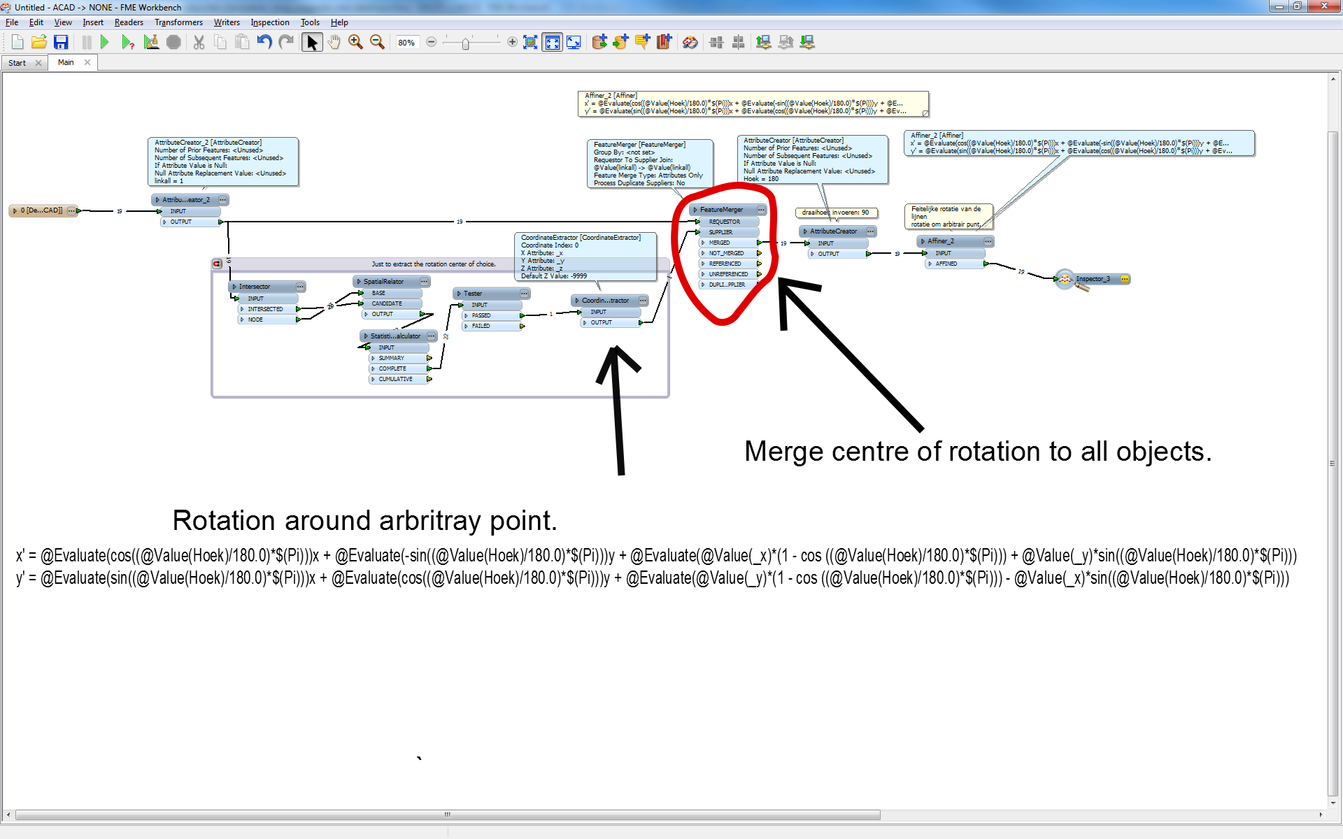
U can extract the coordinate from the location u wish to use as rotationcenter.


The use a 2d affiner to rotate round this point.


Here is the math for the 2d affiner:


Affiner_2 nAffiner] x' = A:   @Evaluate(cos((@Value(Hoek)/180.0)*$(Pi)))x


B:  @Evaluate(-sin((@Value(Hoek)/180.0)*$(Pi)))y 


C:  @Evaluate(@Value(_x)*(1 - cos ((@Value(Hoek)/180.0)*$(Pi))) + @Value(_y)*sin((@Value(Hoek)/180.0)*$(Pi)))


y' =


E:  @Evaluate(sin((@Value(Hoek)/180.0)*$(Pi)))x 


F:  @Evaluate(cos((@Value(Hoek)/180.0)*$(Pi)))y +


G:  @Evaluate(@Value(_y)*(1 - cos ((@Value(Hoek)/180.0)*$(Pi))) - @Value(_x)*sin((@Value(Hoek)/180.0)*$(Pi)))


Hoek = Angle (dutch) of rotation. In your case 180. I would do this using a creator.


(_x,_y)  center of rotation.


U need to group the objects and ID the groups.


Extract the coordinates of the point of rotation.


Then merge the rotation point to the all the objects in a group.D


U can do that using a unconditional merger. ( i create a attribute on all objects like LinkAll+1 and later use it to merge all)


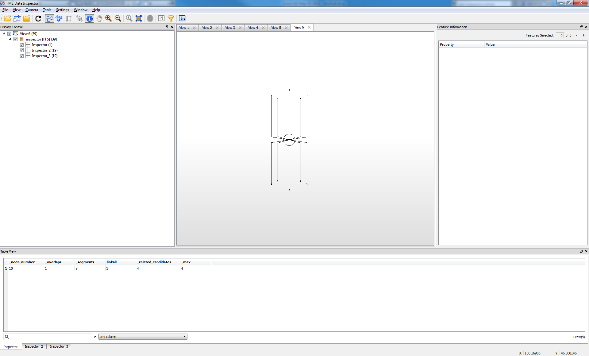
When u do this, each object should now have the same rotationcentre.


Now u can aply the 2d affiner on them.


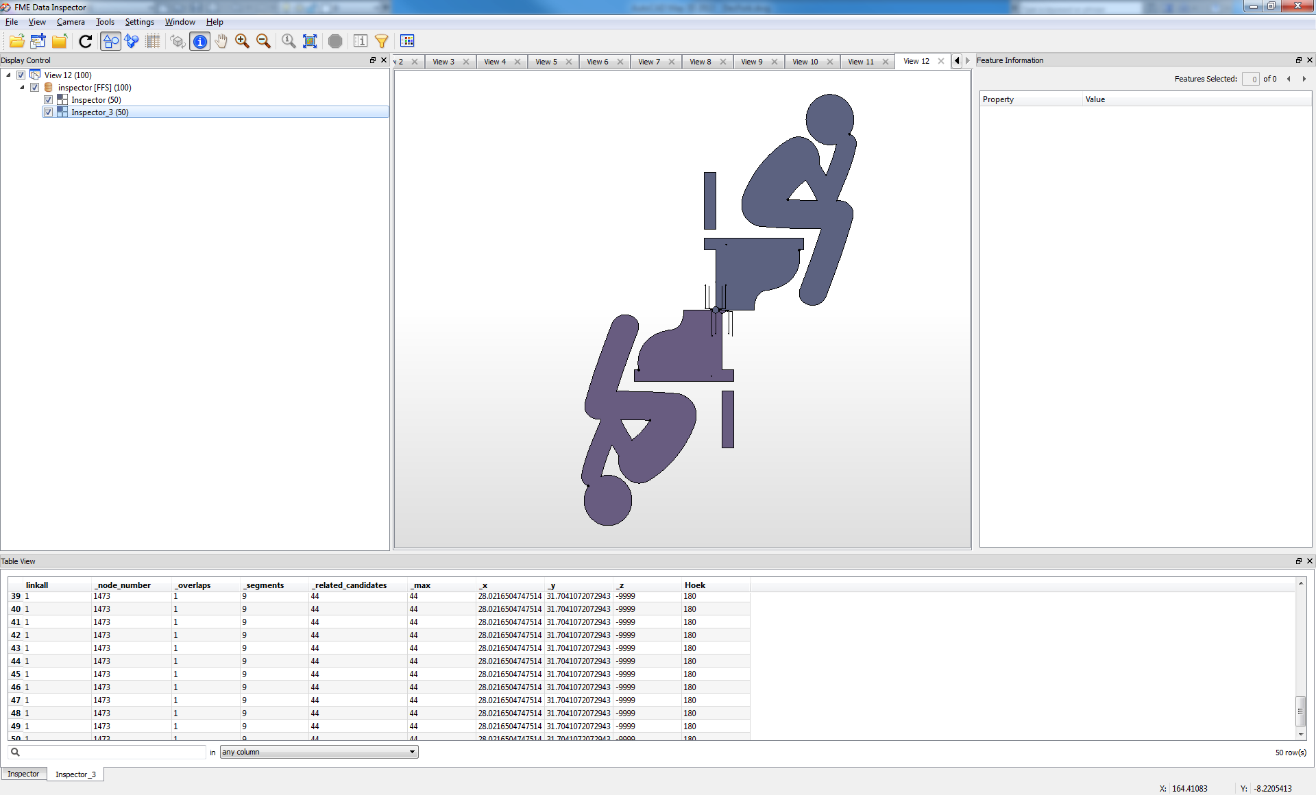
Rotate these by 180


adn rotated.


workspace used:


Gio


i forgot to mention.


I have entered  Pi in a global parameter. (navigator pane, user parameter create)


have funs!


works on any graphics or geometric object (collection):


;)
Enjoyable graphics, Gio :)


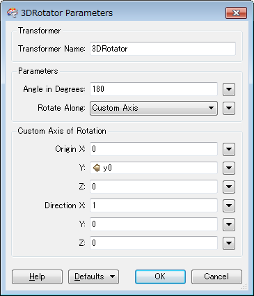
Alternatively, the 3DRotator with this settings can perform "flip" after calculating origin Y of the rotation axis.


y0 = (ymin + ymax)*0.5


Yes, good posture and place for tought...


That is a flipping or a mirror operation trough a mirror-axis. And one is required to aggregate objects.


Without need for aggrtegation:


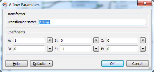
2d affiner:


this is line trough y=0


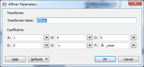
Line trough bottom of objectgroup u need to use 2d affiner to move,


or multiply move matrix with mirror matrix.


My example was a rotator around arbitrary axis.
This is affinre same as your 3d rotator, without need for aggregating.


After boundsextractor.


Using  _ymin will give reflect on bottomline etc.


If u use boundingboxaccumulator then boundsextractor and remerge extracted bounds unconditionaly to input objects u can perform it on all objects in groups.


Hey folks... a HUGE thanks to both Takashi and Gio. Gio you've got some amazing math that goes into this and I was "close" to your approach yesterday but ended up missing out on one or two components. I have to give the best answer to Takashi for ease of use/simplicity. Granted to get the bounds of each box individually I had to create a custom transformer and parallel process by the uniqueID (which consequently was embedded into each each line/point/polygon.)


Thanks again for the nudge in the right direction.
Oh and Gio, your graphics example totally made my day. I pretty much spit my coffee out when I saw it!
Enjoyable graphics, Gio :)


Alternatively, the 3DRotator with this settings can perform "flip" after calculating origin Y of the rotation axis.


y0 = (ymin + ymax)*0.5


Takashi = FME hero...

just what i needed


Reply