I have some Autocad data where the objects are constructed as 3D solids, like this:
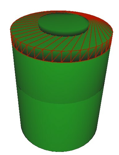
Rund_kumThe 3D data is nice for many uses, but I would also like to extract a simplified version for our GIS databases. The Surface Footprint Replacer will generate a nice polygon, but will also remove the elevation and return 2D data.


Is there a way to get a footprint that retains the elevations of the "top face" of the solid? I most cases this face is flat, but in some cases, like ducts and pipes, this is not the case.

Hi @havmoejbv​,

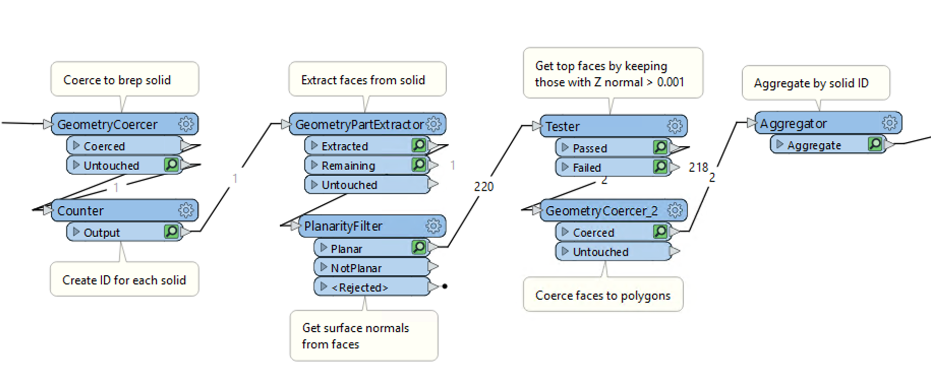
You can extract the top faces of the solid by converting to a brep solid, then extracting the faces from the brep and looking for those whose face normal points up. You can use the following transformers:

Screen Shot 2023-09-26 at 12.14.16 PMI have attached a sample workspace to illustrate the process

Oh, this is nice, and should take me a bit closer to the goal. Thanks @daveatsafe!


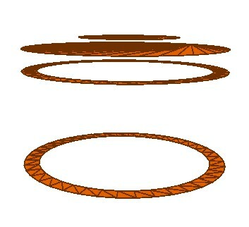
The example I show above is a manhole, consisting of four elements - two concrete rings at the bottom, a concrete top and the opening cover.


Running the workbench above I now get one surface on top of each of these solids :

Rund_kum_topsThe next task would be to get rid of the lower rings (in this case). Ideally, I would want to end up with the two upper surfaces, the top circumference of the manhole and the top circumference of the manhole cover.
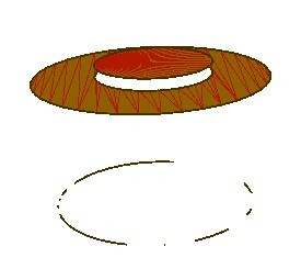
 

I tried using the solid dissolver. This merged the manhole solids and the cover into one object. The extraction above gives the two surfaces I wanted as parts in an IFMEMultiArea , and I'm sure those can be separateed. But, there is some cluttering data at the bottom of some of them. I guess this is due to minor gaps/misalignments between the element solids:

Rund_kum_tops2


Example data attached, containing a manhole and two types of ducts. The ducts do not come through as nice as the manhole, unfortunately... Manhole_duct_example


Oh, this is nice, and should take me a bit closer to the goal. Thanks @daveatsafe!


The example I show above is a manhole, consisting of four elements - two concrete rings at the bottom, a concrete top and the opening cover.


Running the workbench above I now get one surface on top of each of these solids :

Rund_kum_topsThe next task would be to get rid of the lower rings (in this case). Ideally, I would want to end up with the two upper surfaces, the top circumference of the manhole and the top circumference of the manhole cover.
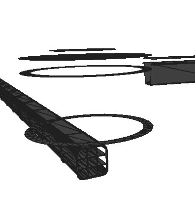
 

I tried using the solid dissolver. This merged the manhole solids and the cover into one object. The extraction above gives the two surfaces I wanted as parts in an IFMEMultiArea , and I'm sure those can be separateed. But, there is some cluttering data at the bottom of some of them. I guess this is due to minor gaps/misalignments between the element solids:

Rund_kum_tops2

Adjusting the normal z component cutoff in the Tester might help eliminating the small pieces. Right now the value is 0.001, which will keep surfaces pointing up even slightly.

This process is really dependent of the source data being proper solids, since that ensures the surface normals point out from the center of the solid. If the source is just a MultiSurface, then we can no longer rely on the orientation of the surface normals.

I think the small pieces are from tiny misalignements of the different solids - the circular base is not a true circle, but made out of many triangles. I did a test where I used CoordinateRounder before the Solid Dissolver, and it seemed to get rid of most of it.


Reply