Hello everyone,
I have a question with regard to preserving the pattern style of hatches in DWG files.
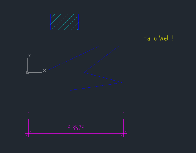
I have a simple DWG file with two lines (blue), one text (yellow), a dimension (magenta), and a polygon (blue) which is filled with a hatch (cyan):

If I now simply read the DWG file with a REALDWG reader and do nothing but write it again with the REALDWG writer,
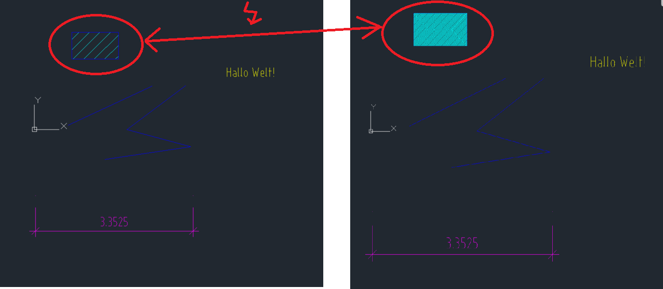
 the hatching pattern looks very different in the result - which is basically because the lines of the hatching pattern are much closer together than they were in the original DWG file:
 More details below.
Does anyone know how I need to parameterize reader and/or writer such that the pattern style of the hatch is preserved 1:1?
In the REALDWG reader, I already linked the read-in DWG file as a "Template File". This helped to preserve the styling of the dimension but unfortunately not with regard to the pattern style of the hatch.
Here some more details:
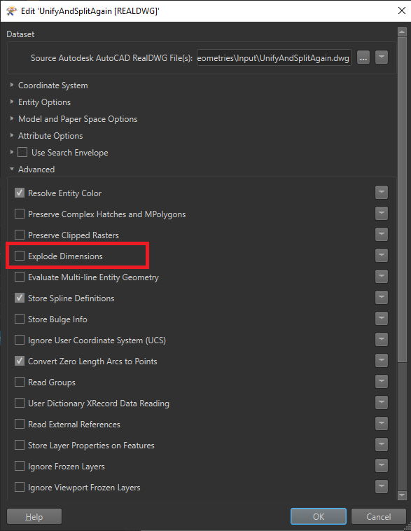
Regarding the parameterization of the REALDWG reader, I only unchecked the "Explode Dimensions" option, everything else if FME Default.
 All the features are read as a single, merged feature type. For this feature type, I exposed the Format Attributes "autocad_layer" and "fme_feature_type":

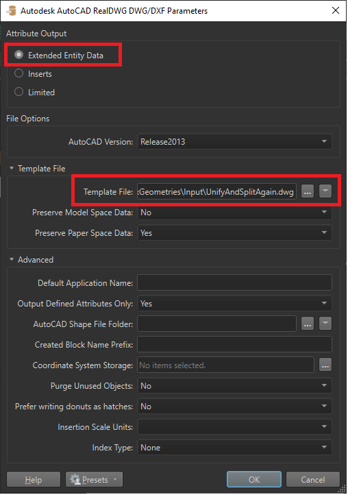
For the REALDWG writer, I did the following:
- set "Attribute Output" to "Extended Entity Data"
- set the DWG file which is read by the reader as "Template File"
 In the feature type writer, the "autocad_layer" attribute is used for the "Layer Name":

The various objects are on different layers in the attached/read-in DWG file:
- 01_Linien: The two lines and the polygon.
- 02_Schraffur: The hatch located within the polygon.
- 03_Text: The text.
- 04_Maßlinie: The dimension.


