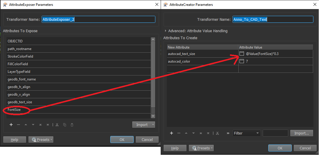
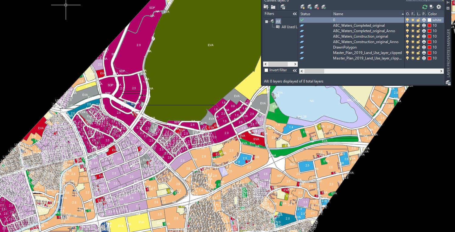
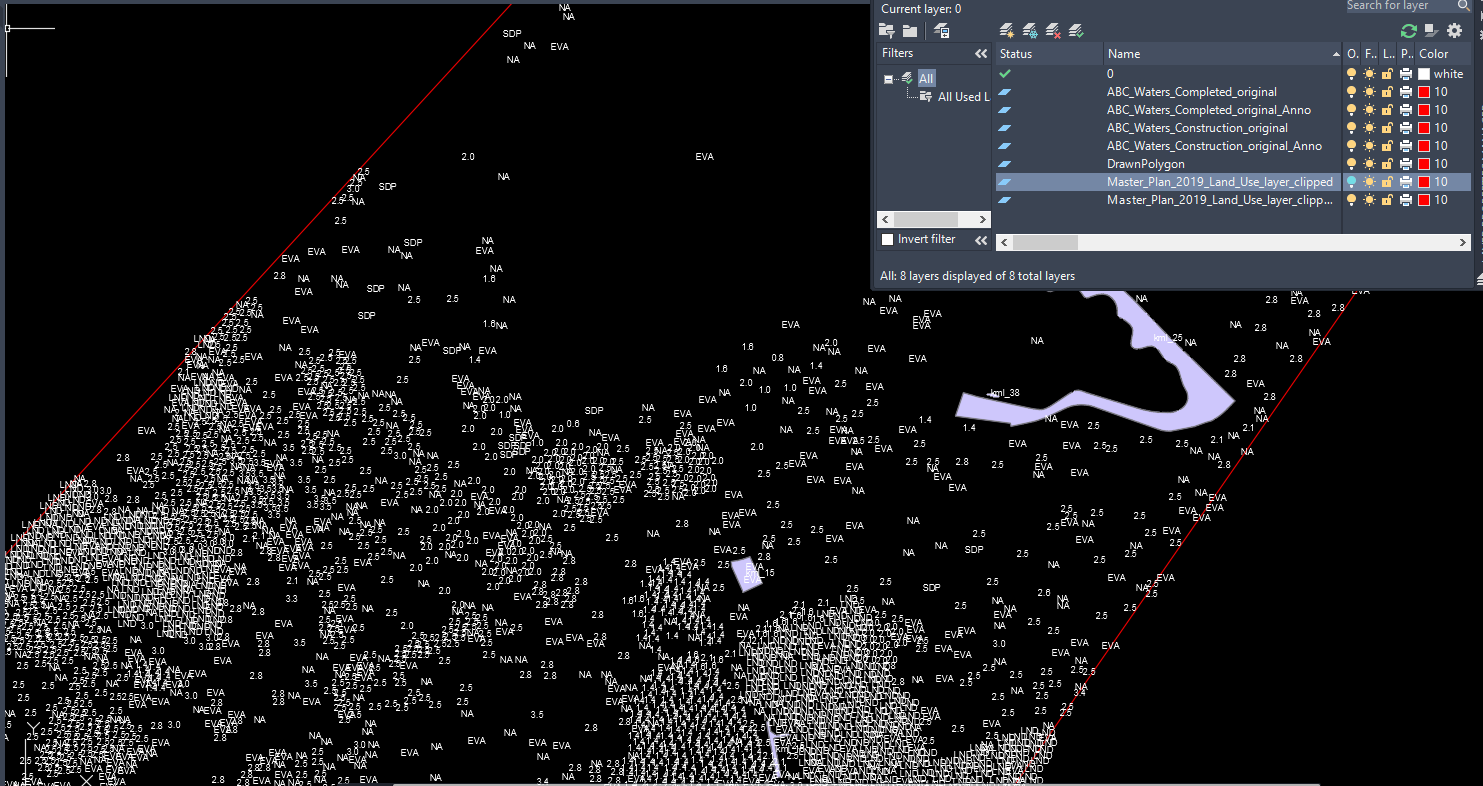
UPDATE: Managed to figure out what went wrong in my comment below the main post (TLDR: Used the wrong transformer and field value from my dataset)
Hi, so I'm trying to convert my annotation layer in my GDB files along side the point, polygon and line layers into DWG.
In my screenshot of my ArcGIS Pro instance, you can see the various labels above my polygons.
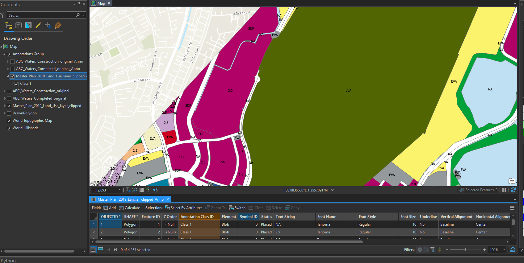
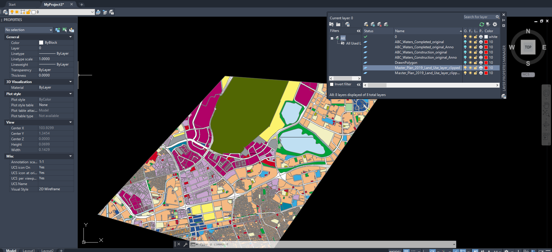
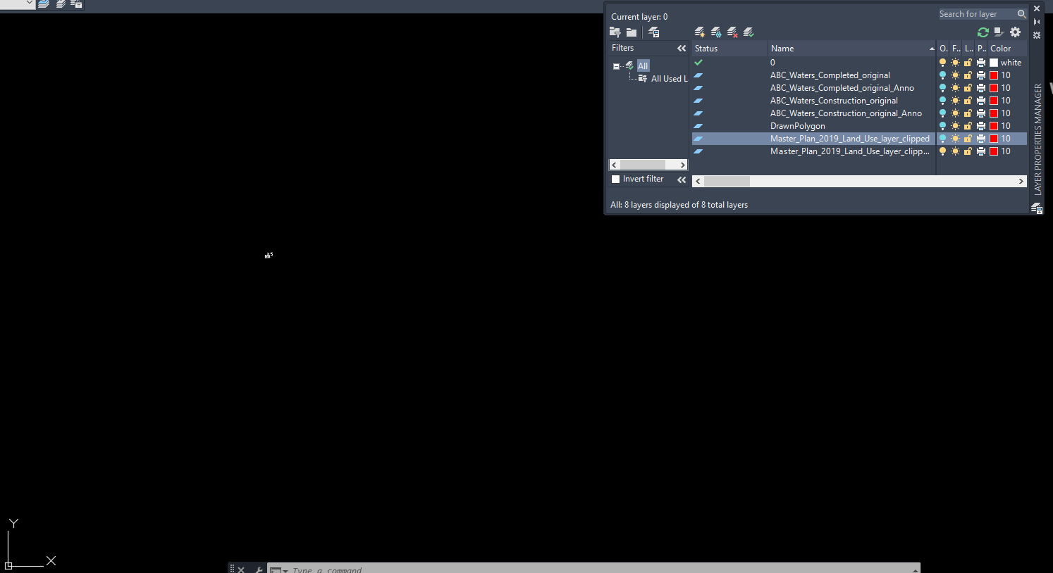 But it looks like only 2 of them passed through to DWG when converted through Workbench.
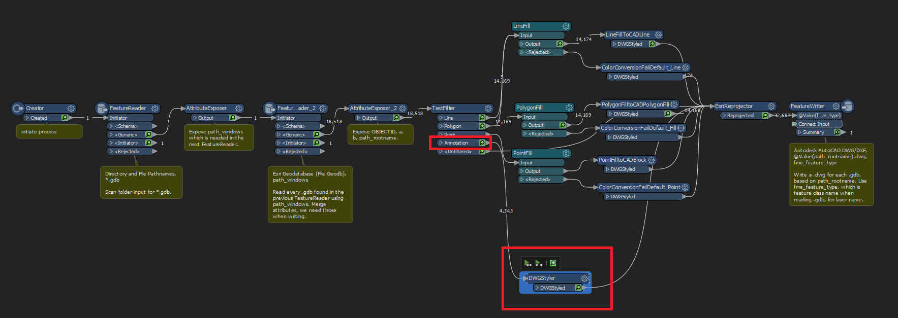 In my current workspace I'm using a LayerTypeField field in the attribute table of all of my layers I wish to converted to sort them into the correct flows (Points, Polygon, Lines, Annotation).
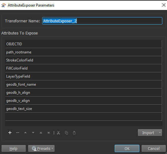
 Those values are exposed via an AttributeExposer parameter as you can see here:
 The annotation layers are very basic ones that are created from running Convert Label To Annotations within ArcGIS Pro itself and an additional field added that just contains "Annotation" as text for filtering purposes in Workbench (LayerTypeField).
At this juncture I just need the formatting of the DWG output to match what it is in the GDB, can someone please advice on what I need to do to get my Annotation data out to CAD properly?


