How this can be achieved in FME?
https://support.esri.com/en/technical-article/000011817
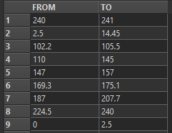
Source data – 2D point geometry with attributes 'FROM' and 'TO' (elevation values stored). The goal is to create 3D lines from those values.


 +5
+5How this can be achieved in FME?
https://support.esri.com/en/technical-article/000011817
Source data – 2D point geometry with attributes 'FROM' and 'TO' (elevation values stored). The goal is to create 3D lines from those values.
Best answer by nielsgerrits
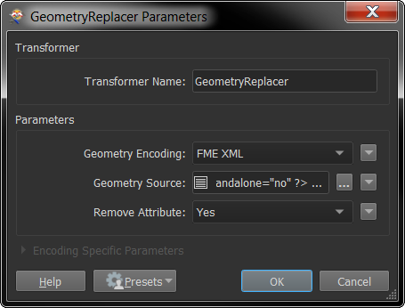
One way to do this is to use a GeometryReplacer.
2D points with elevation interval to 3D lines (2019.1.2).fmwt
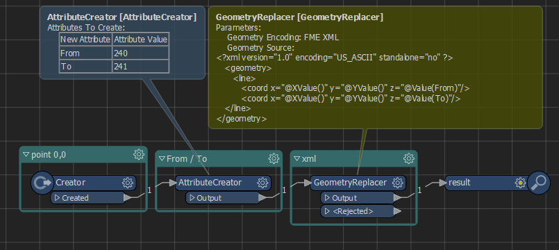
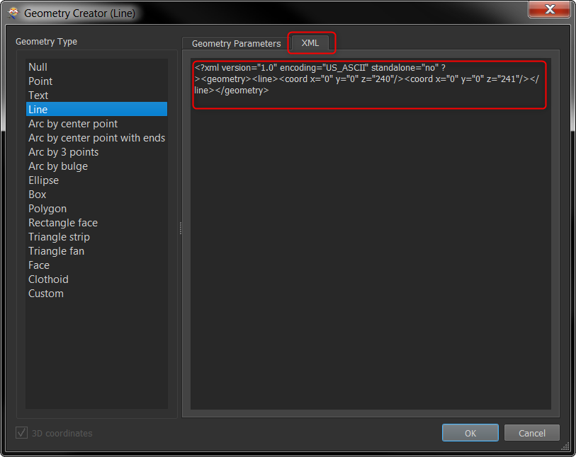
Set the Geometry Encoding to FME XML:
Enter the following XML:
<?xml version="1.0" encoding="US_ASCII" standalone="no" ?>
<geometry>
    <line>
        <coord x="@XValue()" y="@YValue()" z="@Value(From)"/>
        <coord x="@XValue()" y="@YValue()" z="@Value(To)"/>
    </line>
</geometry>
Result:
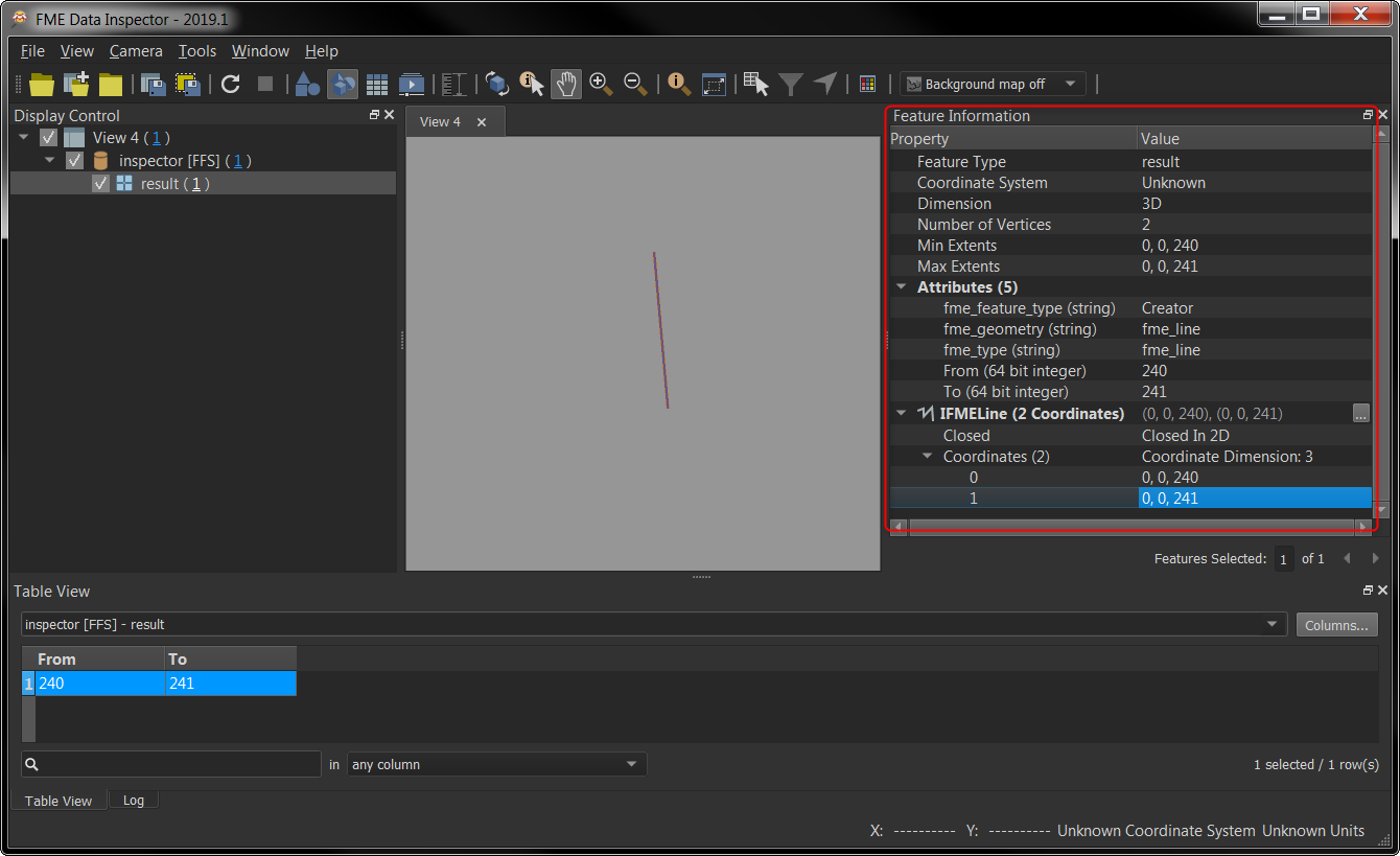
The way to find this is to use a Creator to create a sample geometry, for example a 3D line.
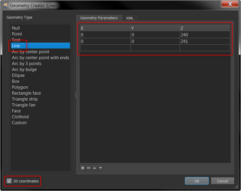
Then go to the XML tab to find the FME XML.
Then replace the coordinates with placeholders.
Enter your E-mail address. We'll send you an e-mail with instructions to reset your password.