Question

FME Data Inspector. Symbol red color, what does it mean ?

  • February 13, 2026
  • 2 replies
  • 75 views

probert1968
Contributor
Forum|alt.badge.img+5

Hi , I am working a lot of the DWG files and I had somebody did the work. So when I  received the DWG files and review them.  I have ArcGIS Pro and I looked at them and I was not sure about the  coordinate system there… so I pulled the file in FME Data Inspector and found them that they are not in the right place I am in Colorado…

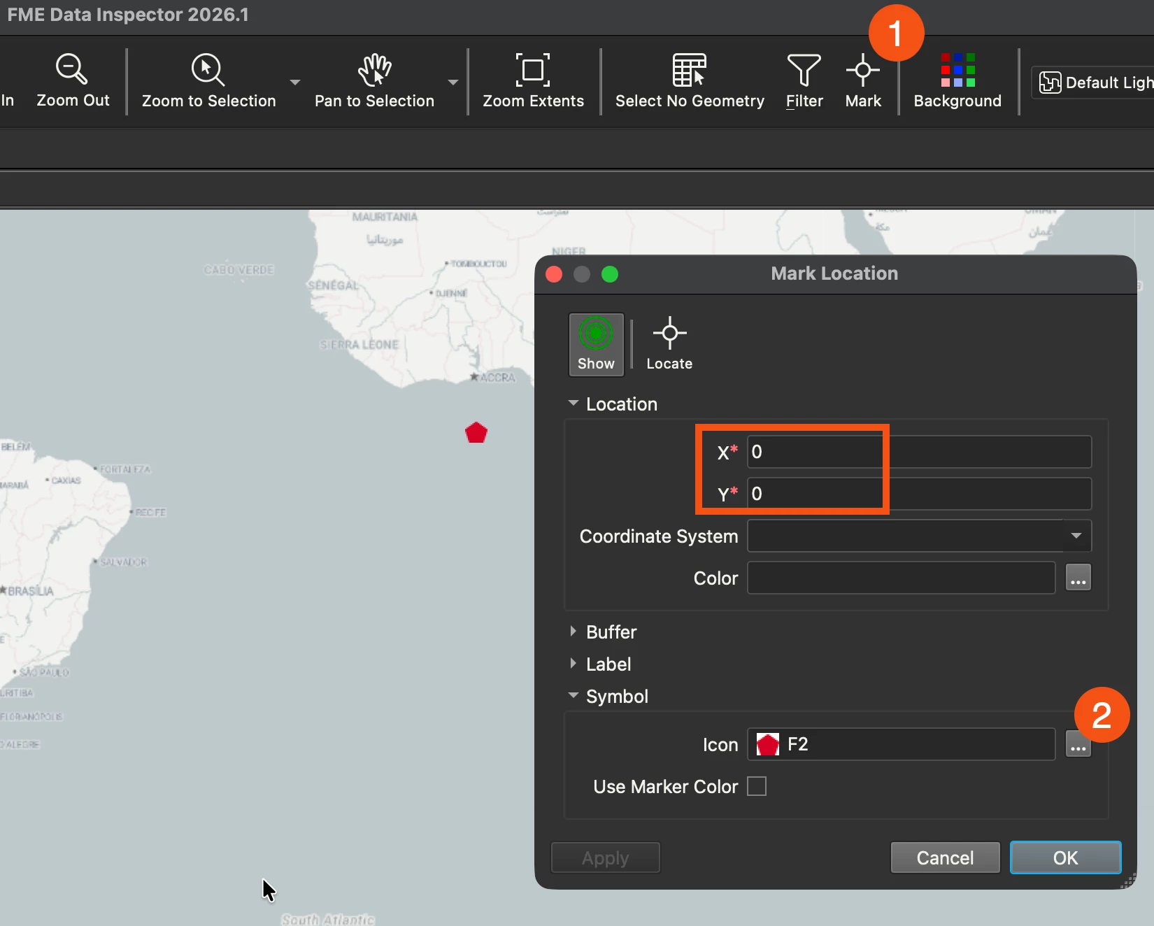
Question first is : What does the red symbol mean here ?

Black square with blue point is where the DWG is.


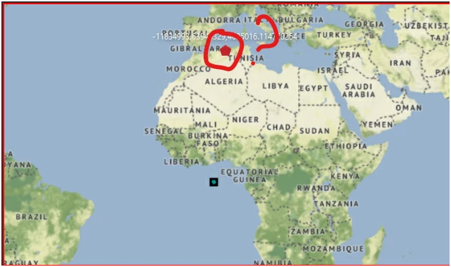
The record information shows the coordinate system is Unknown.

2 replies

jovitaatsafe
Safer
Forum|alt.badge.img+11

Hi ​@probert1968,

It looks like you’ve got ‘Mark’ enabled with a point x,y coordinate in your Data Inspector. If you select the Mark icon in your menu bar between Filter and Background, you should be able to unmark the point by deleting the value in the Icon field:


Hopefully that takes care of the mystery mark!


As for your DWG file, if it’s got a valid PRJ sidecar file containing coordinate system information or if the DWG is produced from an AutoCAD program, FME tries its best to read the coordinate system smartly. If it’s read in as unknown, you’ll need to set the correct coordinate system if the dwg drawing is drawn in the known coordinate system, and you can do that in the reader parameters. 

If you don’t know the coordinate system and it appears correct in ArcGIS Pro, you could export the dwg again from Arcgis Pro with a prj file, then FME should be able to read it as well. Otherwise, you may want to reach out to your DWG provider to get the coordinate system. Hope that helps!

Here’s a few resources that might be helpful for more context:


probert1968
Contributor
Forum|alt.badge.img+5
  • Author
  • Contributor
  • February 20, 2026

Actually, when I went home and relax in front of my computer.  I thought of FME Data Inspector and

google it .  Found some interesting information there… That helped.. But there are a few question I have in my mind is…

When you load the DWG with the wrong place, and I put the correct coordinate numbers to a specific in the mark location , why didn’t the DWG  “on the fly” to that mark area ?  That would be NICE !!!


The DWG shows me the coordinate system numbers shows up in west from Africa was because the numbers done in numbers that they plotted not in the real world coordinates. If you know what I mean.


I found this article from another user that wrote this :  https://community.safe.com/transformers-9/find-the-extents-of-a-dwg-without-reading-in-all-features-3210

I went into FME and wrote the feature to read and found that the numbers are not in coordinate system and their Minimum and Maximum Extent area..

So that helps me to know that the provider gave the wrong .

So I have a lot of them that are in State Plane NAD 83 and I had to convert them NAD 1983 UTM Zone 13N .


I was trying to find a way around a easier way for the next time in the future.


Thanks