
Hello,

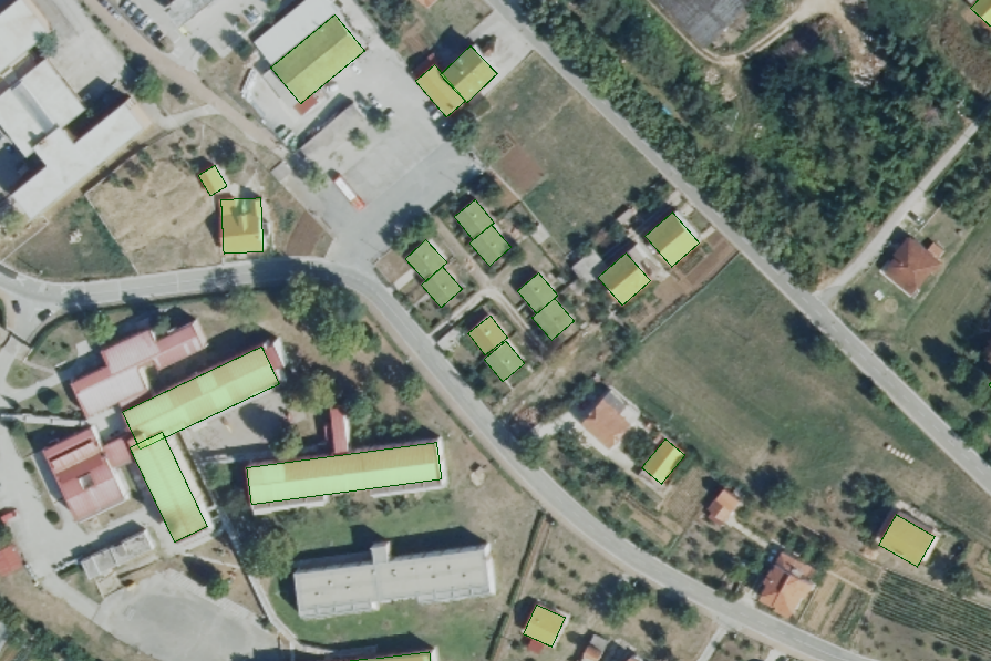
I have encountered a problem, and I hope someone can provide guidance. I need to extract segments of a gable roof. I have attached a picture that illustrates my input data, which consists of polygons indicating the gable roof among other roofs in a digital orthophoto.

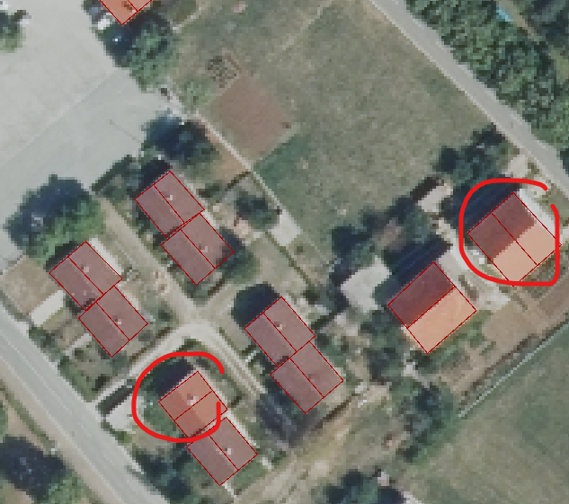
I have utilized the CenterLineReplacer tool, which yielded satisfactory outcomes in most cases. However, I am experiencing difficulties in situations depicted in the image below (the line should be in a different direction):


Does anyone have any ideas on how to solve this?

Thank you in advance for your assistance.

Hey there @pej.k, you might find there are multiple ways to approach this problem in FME, as the CentrelineReplacer could be promising as well. Have you found a way to isolate or extract buildings with incorrect roof geometry yet? Or are we visually identifying these right now? 

If you can separate the incorrectly structured roofs into 2 groups (eg. so the roof lines per group are consistent, one group for the incorrect peaks going side-to-side, the other for incorrect peaks going back-to-front). We can try using the 'Number of Row/Column' parameters in the Tiler to change roof orientation (eg. or redraw the peak). You would require a separate Tiler for each data stream or group. Note - depending on how your geometry is organized, we might need to aggregate/deaggregate along the way. 

If you give this a try and get stuck somewhere, feel free to reach out with an update! It might be helpful if you can share a small sample of the input as well. Happy to help, Kailin. 


A Challenging problem indeed

The CenterLineReplacer will put the center line in the direction parallel to the longest edge. Without any more information there is really no way to tell which way the line should go. 

You could try and identify potential problem buildings/roofs by looking at the ratio of one length vs the other. If the lengths are close/within a certain ratio you could mark these as unknown and output them for manual validation/edits - This might end up being the fastest approach over trying to figure out a way to get the line direction correct in FME.

Of course if you have other data which can add information (surface model) you might be able to automate the whole process but this might get pretty tricky and you might still be faster to just do these problem ones manually.


This would likely take quite a bit of testing, but…..

Atleast in your sample, it looks like each side of the gables might have distinct RGB values we can key off of. Pick one of those sides (probably the lighter side?). If these values are mostly consistent, you could replace just those values with ‘1’ using a RasterCellValueReplacer. Make everything else NoData or ‘0’. With a RasterCellCoercer set to the polygon output, vectorize the ‘1’ cells and then dissolve them with a Dissolver. Get the center line of those vectorized cells, and compare the azimuth to the azimuth of the centerlines you’ve produced already. They should be similar. If they are ~90° out of sync, you know to rotate the original building somehow.


Hello @dustin@virtualcitymatt and @kailinatsafe  thank you for your responses and assistance. In order to meet my deadline, I separated the roofs with incorrect structures and went over them manually. Although this was the quickest solution, I will try out all of the suggested approaches in the future.

Thank you all once again for your valuable input.


Reply