Solved

Moving lines and keeping the line's geometry


Badge +1

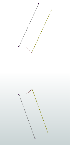
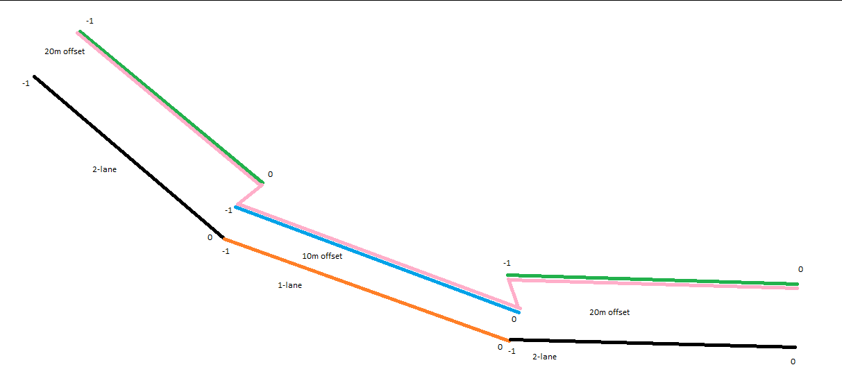
I need some help with this problem below. As seen below the lines have diffrent attribute ID’s 1,2 and 3. The lines 1 and 3 are moving correctely as a offet 10 meter from their first location, as seen in the picture to the left. But line number 2 are not moving as an offset, as it is an exit ramp with different attributes than line 1 and 3. I want line number 2 to move with line 1 and 3, so they are connected in the same way as the right picture, meaning same direction and shape. I already have a dataset as the right version and my first thought is to create a point layer with start- and endpoints of each line and make them always connected as line 1 and 3 are moving. How should I solve this problem as easy as possible. I have a large roadmap of these lines and problems, so this is just an example. 


icon

Best answer by jkr_wrk 17 April 2024, 14:26

View original

12 replies

Userlevel 4
Badge +13

You say that line 2 is not moving because it is an off ramp and has different attributes than the others, so is your offset distance different/dependent on some attribute? Or are you offsetting everything to 10m?

Userlevel 3
Badge +16

If you’re offsetting everything in the same direction 10m, then the Offsetter will do that and retain the network. It sounds like you are trying to offset each line in a different direction, which means that Line 2 needs to get longer.

Does the OffsetCurveGenerator work for you here? 

Badge +1

I’m offsetting to 10 meters, as it should be 10 meters between each line/lanes.

Line 2 has a attribute that refers to “1 lane roadway” and the others lines (Line 1 and 3) refers to “2 lanes raodway”, se below.

1 lane roadway=10 meters offset from reference line

2 lanes roadway=20 meters offset from reference line (but 10 meters from the 1 lane roadway)

I can´t change the attribute for Line 2, beacuse it would be to much manually work for me(as it is a roadmap) so i need somthing that connects points and lines togheter as a move one line correctely. 

Userlevel 4
Badge +18

Is this the result you are looking for:

The black lines are offset with 20m to the green position. The orange line is offset with 10m to the blue location. And then the points are connected so the pink line would be the end result.

You need to somehow find out what the order of lines is that is connected. Maybe with a NetworkTopologyBuilder and then move the lines and create vectors between the lines in the same order as the old lines are connected?


Userlevel 4
Badge +18


Badge +1

Thank you @jkr_wrk

I think this will work :) 

What do you mean with expose the “node list”?

Badge +1

@jkr_wrk  

could you please provide the parameters for each transformer?

Userlevel 4
Badge +18

Forgot to include the most important transformer:


This creates a _nodes{} list that is unexposed for some strange reason.

Badge +1

@jkr_wrk Thank you it helped


How is the tester parameters defined?

Userlevel 4
Badge +18

Split on index 0 and 1 from the listExploder:


Badge +1

@jkr_wrk thank you

what do you mean with the last step “connecting lines” and “offset lines”?

i’ve received points from the “vertex creator 3” but from there i’m stucked :( 

Userlevel 4
Badge +18

The first VertexCreator is set on Replace with Point, and the second VertexCreator is set on Add Point.

This way it creates a line from point 1 to point 2.

And at the end you have 2 sets of lines. The original Offset lines and the set with lines that are the connecting lines between the Offset lines.

I did not test, but i think it will also create lines between lines with the same offset. This will be lines where the two points are on the same spot, so with zerro length. You should filter those out.

Reply