Hi @katt,
Neat question! This had me thinking in 3D space and I will not lie I got my XYZ axes confused a time or two. I expect that creating the solid is the tricky part, and after that the Clipper will allow you to clip a point cloud with a solid. FME 2021.2 should be able to do this already, but if you're interested, check out FME 2022 for improved Clipper capabilities and more geometry clipping support. Here's what you can do to create the solid:
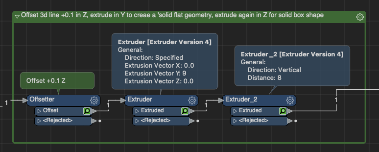
1- Offset your line +0.1m above where the line began using an Offsetter.
Units are determined by the coordinate system, so if your data has a coordinate system already, set it in the reader and ensure it's one that is in meters or else you'll need a Reprojector. If your data doesn't have a coordinate system already defined, you will need to either geolocate it or use a LocalCoordinateSystemSetter
2- Use an Extruder to extrude in the Y axis to create the base flat solid geometry (width)
3- Use another Extruder to extrude in the Z axis the height
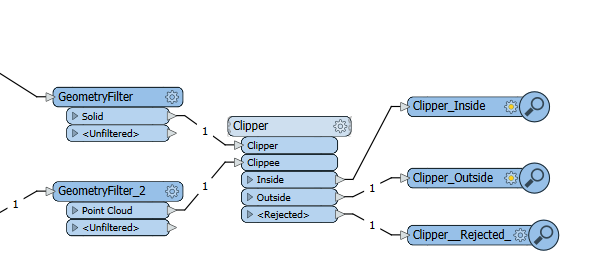
4- Clip your point cloud with the solid geometry using a Clipper. Check at this step that both point cloud and solid are in the same coordinate system as there needs to be overlap for clipping to be successful.
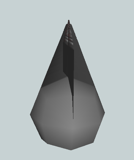
Here's a mockup example I created with a random 3d polyline:This is what the result looks like at each step:
Hopefully that provides some starting ideas to work with!
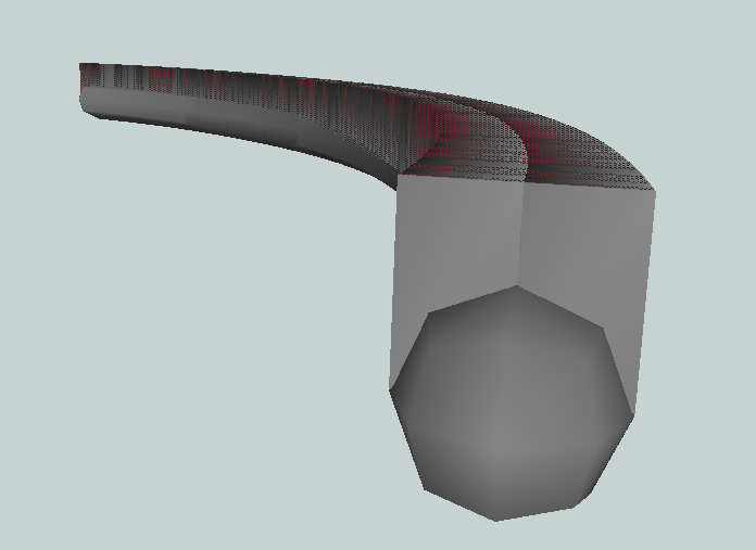
Thank you @jovitaatsafe for your help. I applied what you suggested. I also used a solid bufferer for comparison. You can see on the image two results: 1.in blue: I used an offsetter of 0.1. and then a solid bufferer of 4.5 around the line and 2. in grey: I used the transformers you suggested. The result in grey looks correct for the height(z-value) (grey has a height of 8 above the line, the blue of 4.5). But the length of the grey result is not as expected. Instead of creating 4.5.m left of the line and 4.5m right of the line, it created 9m on one side of the line. Any way to change this ?
Hi @katt, for the length, perhaps you could split it into two operations using the Extruder. Since the Extruder only extrudes from the starting point outwards in one axis, you could make the half point 4.5m for the first Extruder, then offset the initial line the same 4.5m for a new starting point and then extrude again 4.5m in the same direction. Once you have these two halves, you can use a SolidDissolver to make it into one solid.
(Pro tip: if you're using FME 2022, there's a new official SolidDissolver to replace the FME Hub custom transformer if you wanted to give that a try!)
Thank you @jovitaatsafe for your help. I applied what you suggested. I also used a solid bufferer for comparison. You can see on the image two results: 1.in blue: I used an offsetter of 0.1. and then a solid bufferer of 4.5 around the line and 2. in grey: I used the transformers you suggested. The result in grey looks correct for the height(z-value) (grey has a height of 8 above the line, the blue of 4.5). But the length of the grey result is not as expected. Instead of creating 4.5.m left of the line and 4.5m right of the line, it created 9m on one side of the line. Any way to change this ?
Thanks so much @jovitaatsafe This solution created the solid I wanted. The next step is to clip my point cloud by this solid. When I used the clipper, it was rejected with following error "INVALID_CLIPPER_GEOMETRY_TYPE". Does the clipper transformer not accept solids as clipper? How to resolve this case? thanks.
Thank you @jovitaatsafe for your help. I applied what you suggested. I also used a solid bufferer for comparison. You can see on the image two results: 1.in blue: I used an offsetter of 0.1. and then a solid bufferer of 4.5 around the line and 2. in grey: I used the transformers you suggested. The result in grey looks correct for the height(z-value) (grey has a height of 8 above the line, the blue of 4.5). But the length of the grey result is not as expected. Instead of creating 4.5.m left of the line and 4.5m right of the line, it created 9m on one side of the line. Any way to change this ?
@katt, woohoo! Glad to hear that the first part worked out for you!
For the Clipper, can you confirm that you have the point cloud connected to the clippee port and the solid(s) connected to the clipper port? According to our Clipper Geometry Support Reference, you should be able to clip point clouds using solid(s), but the reverse doesn't work, so point clouds can't clip anything else.
Thank you @jovitaatsafe for your help. I applied what you suggested. I also used a solid bufferer for comparison. You can see on the image two results: 1.in blue: I used an offsetter of 0.1. and then a solid bufferer of 4.5 around the line and 2. in grey: I used the transformers you suggested. The result in grey looks correct for the height(z-value) (grey has a height of 8 above the line, the blue of 4.5). But the length of the grey result is not as expected. Instead of creating 4.5.m left of the line and 4.5m right of the line, it created 9m on one side of the line. Any way to change this ?
@jovitaatsafe I know that part of the point cloud is inside and some is outside of the solid as I used a different but less efficient method to clip before. So I don't understand why I get a rejection code now.
Thank you @jovitaatsafe for your help. I applied what you suggested. I also used a solid bufferer for comparison. You can see on the image two results: 1.in blue: I used an offsetter of 0.1. and then a solid bufferer of 4.5 around the line and 2. in grey: I used the transformers you suggested. The result in grey looks correct for the height(z-value) (grey has a height of 8 above the line, the blue of 4.5). But the length of the grey result is not as expected. Instead of creating 4.5.m left of the line and 4.5m right of the line, it created 9m on one side of the line. Any way to change this ?
From the error message, something could be wrong with the solid. Can you try adding a GeometryValidator after the GeometryFilter and set the 'Set of Issues to Detect' as Surfaces and Solids. That will check to see if there are any issues with the geometry. If it passes the check, you can send the Passed and Repaired port to the Clipper and see if that improves things.
Another thing you could try is to have a go with FME 2022 and be sure to upgrade the transformer for full new functionality and see if it may handle it better. (To upgrade the transformer, go to the Navigator > Upgradeable Transformers > Clipper and right click to upgrade).
If none of those work, if you're able to share your workspace and sample data, I can try to have a look as well.
Thank you @jovitaatsafe for your help. I applied what you suggested. I also used a solid bufferer for comparison. You can see on the image two results: 1.in blue: I used an offsetter of 0.1. and then a solid bufferer of 4.5 around the line and 2. in grey: I used the transformers you suggested. The result in grey looks correct for the height(z-value) (grey has a height of 8 above the line, the blue of 4.5). But the length of the grey result is not as expected. Instead of creating 4.5.m left of the line and 4.5m right of the line, it created 9m on one side of the line. Any way to change this ?
Hello @jovitaatsafe , I just applied the same script (incl the parameters + settings you suggested) to two different lines and I get two results completely different of a solid. I also created a solid buffer (4.5m) around the lines to facilitate comparison. The first is the result as expected, but the second isn't. Why are the results that different ?
Thank you @jovitaatsafe for your help. I applied what you suggested. I also used a solid bufferer for comparison. You can see on the image two results: 1.in blue: I used an offsetter of 0.1. and then a solid bufferer of 4.5 around the line and 2. in grey: I used the transformers you suggested. The result in grey looks correct for the height(z-value) (grey has a height of 8 above the line, the blue of 4.5). But the length of the grey result is not as expected. Instead of creating 4.5.m left of the line and 4.5m right of the line, it created 9m on one side of the line. Any way to change this ?
Unfortunately it's hard to say why without seeing the second line and how it differs from the first. I'm not certain, but the resulting solid looks like it only extruded in one direction, vertically rather than both vertical and horizontal.
Some questions to consider when checking the workspace with the second line are:
- what 3D orientation is the new line in? How is it different?
- Did you rerun the whole workspace entirely or were some of the feature caches already loaded? Try going to Run > Rerun entire workspace to rule out feature caching.
- run the workspace with feature caching on and inspect the output at each transformer to isolate where it may be going wrong. Can you put any checks in place to handle the geometry the way you want it to come out?
Thank you @jovitaatsafe for your help. I applied what you suggested. I also used a solid bufferer for comparison. You can see on the image two results: 1.in blue: I used an offsetter of 0.1. and then a solid bufferer of 4.5 around the line and 2. in grey: I used the transformers you suggested. The result in grey looks correct for the height(z-value) (grey has a height of 8 above the line, the blue of 4.5). But the length of the grey result is not as expected. Instead of creating 4.5.m left of the line and 4.5m right of the line, it created 9m on one side of the line. Any way to change this ?
@jovitaatsafe , maybe you can help me out ? I attached a fmw with a line and the transformers as discussed. The outcome of the extruder should be similar to the one of the solid bufferer except for the height. But it isn't the case. Maybe you have an idea why?! Thx.
Thank you @jovitaatsafe for your help. I applied what you suggested. I also used a solid bufferer for comparison. You can see on the image two results: 1.in blue: I used an offsetter of 0.1. and then a solid bufferer of 4.5 around the line and 2. in grey: I used the transformers you suggested. The result in grey looks correct for the height(z-value) (grey has a height of 8 above the line, the blue of 4.5). But the length of the grey result is not as expected. Instead of creating 4.5.m left of the line and 4.5m right of the line, it created 9m on one side of the line. Any way to change this ?
@jovitaatsafe Could you help me with the example above I posted a month ago?
Thank you @jovitaatsafe for your help. I applied what you suggested. I also used a solid bufferer for comparison. You can see on the image two results: 1.in blue: I used an offsetter of 0.1. and then a solid bufferer of 4.5 around the line and 2. in grey: I used the transformers you suggested. The result in grey looks correct for the height(z-value) (grey has a height of 8 above the line, the blue of 4.5). But the length of the grey result is not as expected. Instead of creating 4.5.m left of the line and 4.5m right of the line, it created 9m on one side of the line. Any way to change this ?
Hi @katt
My apologies for letting this question fall through the cracks, I had it in my mind to link Dave's answer from your other question as the PipeReplacer is likely the best solution, but currently lacks orientation control and it has been filed as an enhancement request. From there you could possibly offset and clip to get a shape of 8x9 instead of 9x9.
The way that I have suggested would work for a single line, but as soon as we add other lines in a more complex network or in other orientations this no longer works as well since we're manually extruding lengths. I believe you'll be able to get the best results when the enhancement to the PipeReplacer to allow for orientation control has been addressed and hopefully implemented. In the meantime it might be better to model the pipe geometry outside of FME before manipulation it further in FME.
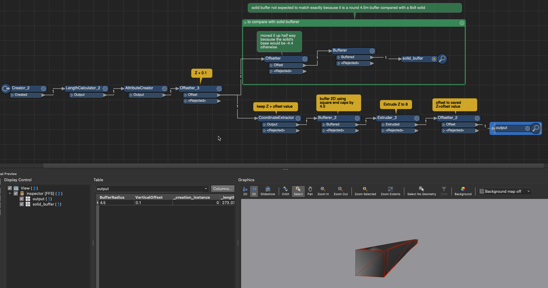
I did some more testing and managed to get this particular line wrangled into the right size and shape using a square buffer thanks to a workspace suggestion by my colleague Chris B. I've also adjusted the solid buffer to the correct Z height for comparison to make sure the base of the solid is +0.1 from the ground/starting value. The two objects won't line up perfectly, but that's because the buffered solid is 9m diameter while the created solid is 9x8. I've attached the workspace in case that sparks any other ideas, but I would think that the PipeReplacer would be a better fit once it has added orientation control.