I am quite new to this forum, and FME in general. Can any nice pro in here help me with this one?
I am trying to work on an electric network map, which is of very bad quality. It´s in dxf-format only, everything in one layer, no linetypes, low geometric consistency and the only thing separating different lines are their colors.
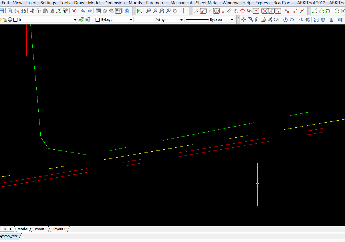
Underground cables are supposed to centerline-dashed lines but the dxf only gives them to me as a great number (~500k) of lines of ABOUT 1 and 5 meters length following each other at ABOUT the same azimuth.
So, what I would like to do is somehow replace these multitudes of lines with fewer lines, which I then could assign centerline as linetype.

The different colors represent different voltages.
The short lines length are ranging from 0.9992-1.0007 and the longer ones from 4.9992-5.0007.
What makes this one tough for me to figure out is that he azimuths/angles of the seemingly parallel lines are not equal. For example in the picture above:
Long upper red lines: autocad_angle = 9.7053
Short upper red lines: autocad_angle = 9.6791
Long lower red lines: autocad_angle = 9.7072
Short lower red lines: autocad_angle = 9.7357
I was thinking of sorting out the lines of ca 1 and ca 5 in length by using Tester (BETWEEN) and separating the different voltage lines through AttributeFilter. Then somehow using Snapper, LineJoiner and AzimuthCalculator to simplify, but it beats me how to make the red lines connect to become two (almost) parallel lines and not "cross-snap" to each other.
Of course the network contains lines of all ranges of angles...
If anyone has any ideas, thanks a lot!


