This is part of larger script, where the goal is to generate multiple rotation alternatives for a series of polygons.


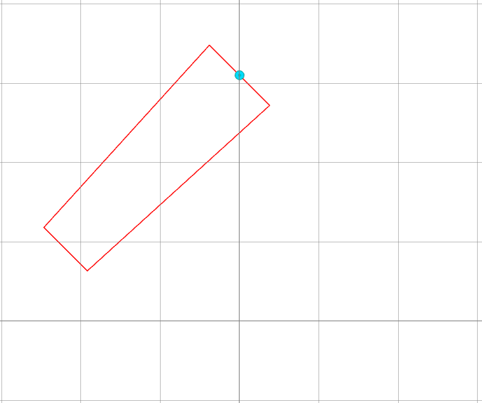
In this case, I have a 5-vertex closed polygon, where the midpoint of its "tip" is located in the center of the axes (0,0).


What I am trying to achieve is, after generating a series of rotations from an arbitrary point -located in the feature's upper segment (see blue point in pictures below)- to calculate the shift in coordinates the rotation caused, in order to move the whole polygon accordingly afterwards, so the "tip" midpoint of the rotated polygon is again place at the center of the axes.


Please see pictures below for better understanding :
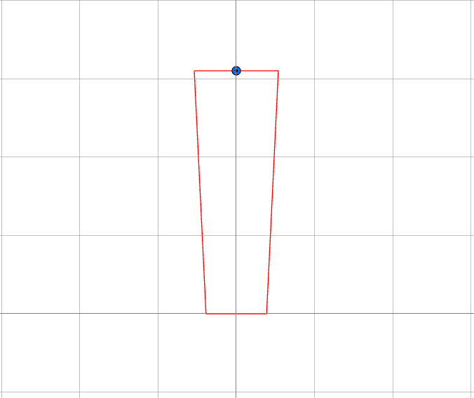
1_Original_Position2_rotated_45d3_moved_backIn picture one, the original position of the polygon is shown, where the midpoint of the tip is located in the center of axes.

In the second picture, a clockwise rotation of 45 degrees has been applied, where the blue point has been used as an "anchor" (0,31).

In the third picture, the shift has been implemented, where the midpoint of the tip of the polygon has been replaced to the center of the axes. 

After doing some research, the affiner transformer seems to be a good use, but not sure how to implement it - especially when the rotation has not happened from the center of the axes.


The complete feature consists of multiple polygons, but the rotation is being applied only to specific ones, like the ones in the picture. I believe that if the same shift is applied to the rest of the parts, like the one in picture nr.3 , they will also be moved accordingly.


Any help would be really appreciated!


Thank you very much!


I do not understand. Do you want to calculate the rotation angle and shift from the first and second polygon, to undo the shift?


With the Rotator, you can rotate around X = @XValue() and Y = @YValue() (the coordinates of the first vertex of the feature). This seems easier than your workflow, but I may have misunderstood.


I do not understand. Do you want to calculate the rotation angle and shift from the first and second polygon, to undo the shift?

Hi, thanks for the quick reply!


Just to clarify a think that might lead to misunderstanding, the blue point on the pictures above is the "anchor" where the rotation is happening from, and the center of the axes (0,0) is the midpoint of the segment across.


In all three pictures, it is the same polygon. First one is the original position, second after it has been rotated (45degrees) and third one after its tip has been placed back in the center of the axes.


I recreated manually all the steps that I would like to automate, in order to provide a better understanding of the process.


Hopes this provides a bit more clarity, otherwise please let me know to elaborate more - as I also struggle to get my head around it 😅

But why not just rotate around 0,0 instead?


Hi, thanks for the quick reply!


Just to clarify a think that might lead to misunderstanding, the blue point on the pictures above is the "anchor" where the rotation is happening from, and the center of the axes (0,0) is the midpoint of the segment across.


In all three pictures, it is the same polygon. First one is the original position, second after it has been rotated (45degrees) and third one after its tip has been placed back in the center of the axes.


I recreated manually all the steps that I would like to automate, in order to provide a better understanding of the process.


Hopes this provides a bit more clarity, otherwise please let me know to elaborate more - as I also struggle to get my head around it 😅

Because the Anchor is fixed to another polygon feature - where this is where the rotation coming from, as it is the joint.


Even if I did it the other way around -as you suggesting- I would still have to "shift" the other polygon in order to snap it to the joint.


Hi, thanks for the quick reply!


Just to clarify a think that might lead to misunderstanding, the blue point on the pictures above is the "anchor" where the rotation is happening from, and the center of the axes (0,0) is the midpoint of the segment across.


In all three pictures, it is the same polygon. First one is the original position, second after it has been rotated (45degrees) and third one after its tip has been placed back in the center of the axes.


I recreated manually all the steps that I would like to automate, in order to provide a better understanding of the process.


Hopes this provides a bit more clarity, otherwise please let me know to elaborate more - as I also struggle to get my head around it 😅

If you put both features through the Rotator transformer, using the same settings for rotation and origin, both features will be rotated around it and stay connected? I guess it has to do with the day of the week, but I can't understand the bigger picture, which makes it harder to solve.


With the Rotator, you can rotate around X = @XValue() and Y = @YValue() (the coordinates of the first vertex of the feature). This seems easier than your workflow, but I may have misunderstood.

Sure, I am aware of the rotator transformer. I am actually using it to perform all the different alternative rotations. The thing I am looking for is, to generate a formula with how much the rotation shifted my polygon from its original coordinates, in order to place the now rotated feature, back.


Hi, thanks for the quick reply!


Just to clarify a think that might lead to misunderstanding, the blue point on the pictures above is the "anchor" where the rotation is happening from, and the center of the axes (0,0) is the midpoint of the segment across.


In all three pictures, it is the same polygon. First one is the original position, second after it has been rotated (45degrees) and third one after its tip has been placed back in the center of the axes.


I recreated manually all the steps that I would like to automate, in order to provide a better understanding of the process.


Hopes this provides a bit more clarity, otherwise please let me know to elaborate more - as I also struggle to get my head around it 😅

It is correct that in this case, it would be easily solved if you just reversed the rotation origin, and rotated it from the center of axes. But as mentioned, other polygons have to follow suit, which are not being rotated.


Imagine it like an excavator that has to dig in a specific x,y location. The excavator's boom and bucket can be be rotated 360 degrees, but tracks are fixed to a specific heading. There is multiple angles that the upper part of the excavator can have while the lower one is fixed. The rotation origin, in this case is coming from the excavation location (x,y) which is actually the location of the bucket. In order to calculate where the lower part is going to placed for every different angle of the boom-bucket alternative, you need to know how much the rotation shifted the x,y coordinates and apply that offset. This is the formula I am trying to find out.


In the example above, the red polygon is the boom-bucket upper part, the blue point is the fixed tracks of the excavator, and the center of the axis is the digging location.


Hi, thanks for the quick reply!


Just to clarify a think that might lead to misunderstanding, the blue point on the pictures above is the "anchor" where the rotation is happening from, and the center of the axes (0,0) is the midpoint of the segment across.


In all three pictures, it is the same polygon. First one is the original position, second after it has been rotated (45degrees) and third one after its tip has been placed back in the center of the axes.


I recreated manually all the steps that I would like to automate, in order to provide a better understanding of the process.


Hopes this provides a bit more clarity, otherwise please let me know to elaborate more - as I also struggle to get my head around it 😅

Ah ok, you always can calculate it using geometry. If you know the distance from the boom and the angle of rotation, you can calculate the x displacement. Once you have that one, you can also calculate the y displacement from the original endpoint of the boom. Then you can use the offsetter to move both back so the end of the boom is back in the original location.


Hi, thanks for the quick reply!


Just to clarify a think that might lead to misunderstanding, the blue point on the pictures above is the "anchor" where the rotation is happening from, and the center of the axes (0,0) is the midpoint of the segment across.


In all three pictures, it is the same polygon. First one is the original position, second after it has been rotated (45degrees) and third one after its tip has been placed back in the center of the axes.


I recreated manually all the steps that I would like to automate, in order to provide a better understanding of the process.


Hopes this provides a bit more clarity, otherwise please let me know to elaborate more - as I also struggle to get my head around it 😅

Indeed, but if I have to do that to do that for hundreds of locations, then I need a formula that I can insert into the offsetter, that it will place them at the appropriate location automatically - without calculating the x,y displacement for each one of them.


Hi, thanks for the quick reply!


Just to clarify a think that might lead to misunderstanding, the blue point on the pictures above is the "anchor" where the rotation is happening from, and the center of the axes (0,0) is the midpoint of the segment across.


In all three pictures, it is the same polygon. First one is the original position, second after it has been rotated (45degrees) and third one after its tip has been placed back in the center of the axes.


I recreated manually all the steps that I would like to automate, in order to provide a better understanding of the process.


Hopes this provides a bit more clarity, otherwise please let me know to elaborate more - as I also struggle to get my head around it 😅

X = r * cos(45)

Y = r * sin(45)


So if the boom is 3 and the rotation = 45 degrees, the displacements are 2.12m x and 2.12 m y.


Hi, thanks for the quick reply!


Just to clarify a think that might lead to misunderstanding, the blue point on the pictures above is the "anchor" where the rotation is happening from, and the center of the axes (0,0) is the midpoint of the segment across.


In all three pictures, it is the same polygon. First one is the original position, second after it has been rotated (45degrees) and third one after its tip has been placed back in the center of the axes.


I recreated manually all the steps that I would like to automate, in order to provide a better understanding of the process.


Hopes this provides a bit more clarity, otherwise please let me know to elaborate more - as I also struggle to get my head around it 😅

I think this close to the final answer, but not exactly.

For example, in this case, where the rotation took place from the blue point (0,31), the displacement of the opposite part -the tip- which afterwards had to be applied in order to bring it back to the center of the axes, was X≈21 and Y ≈ 9.1.

I think the trick now is, to take into account that the rotation is not happening from the center of the axes, as the formulas above suggest. ​


Hi, thanks for the quick reply!


Just to clarify a think that might lead to misunderstanding, the blue point on the pictures above is the "anchor" where the rotation is happening from, and the center of the axes (0,0) is the midpoint of the segment across.


In all three pictures, it is the same polygon. First one is the original position, second after it has been rotated (45degrees) and third one after its tip has been placed back in the center of the axes.


I recreated manually all the steps that I would like to automate, in order to provide a better understanding of the process.


Hopes this provides a bit more clarity, otherwise please let me know to elaborate more - as I also struggle to get my head around it 😅

What is the lenght of the boom?


Hi, thanks for the quick reply!


Just to clarify a think that might lead to misunderstanding, the blue point on the pictures above is the "anchor" where the rotation is happening from, and the center of the axes (0,0) is the midpoint of the segment across.


In all three pictures, it is the same polygon. First one is the original position, second after it has been rotated (45degrees) and third one after its tip has been placed back in the center of the axes.


I recreated manually all the steps that I would like to automate, in order to provide a better understanding of the process.


Hopes this provides a bit more clarity, otherwise please let me know to elaborate more - as I also struggle to get my head around it 😅

The length of the boom is 31 meters.


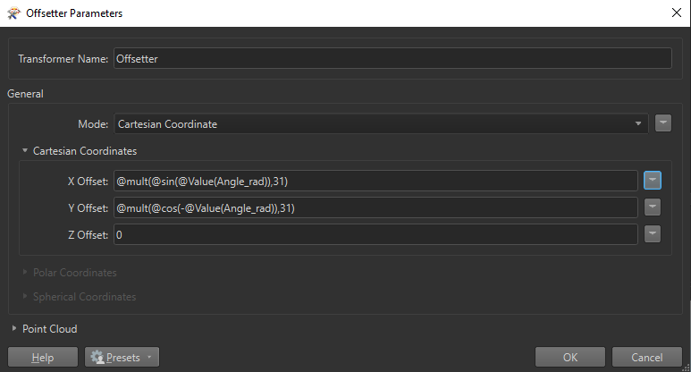
I managed to make it work using the below formula, for when it is being rotated clockwise. The formula was created empirically, and I am not sure why it works - maybe I have to study in more detail the rotation matrices.


Important: Before I apply any rotation, and then the offset by the formulas below, I offset my polygon by X = 0, Y = -31 so the rotation can take place from the center of the axes.


Offset_formula 


Reply