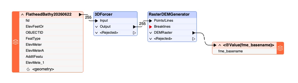
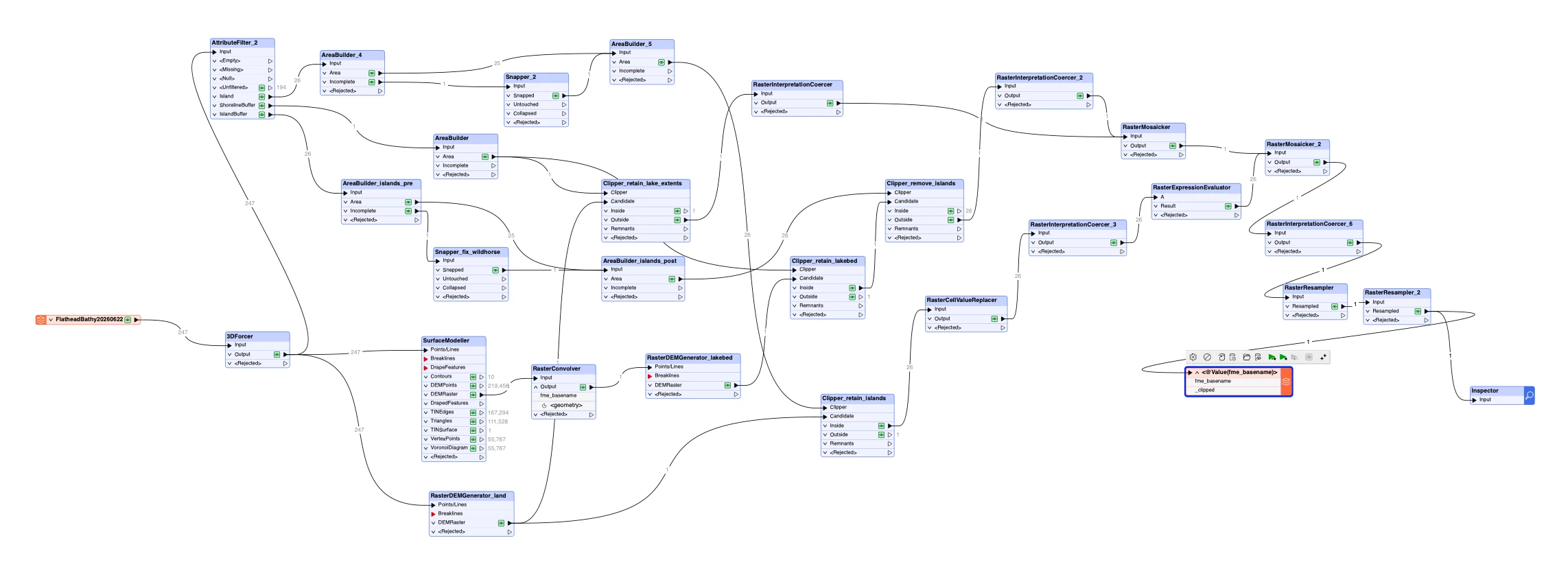
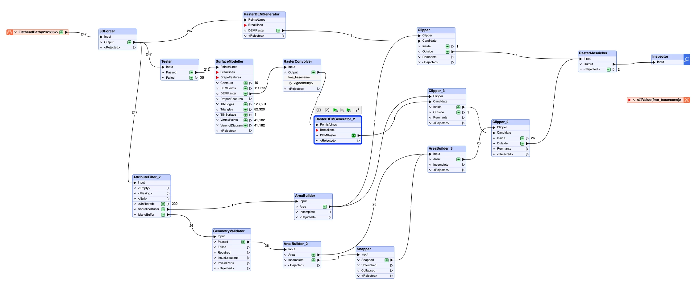
I have a bathymetric shapefile that I’ve adapted for eventual 3D printing. Part of my challenge is the sparsity of contour lines, which creates substantial space between contours. I previously tried GRASS/QGIS/SAGA/etc with limited success. Now I’m trying FME. FME processing is much easier, but the issue I’m trying to solve now is roughness at contour edges. This is the workflow I’m using:
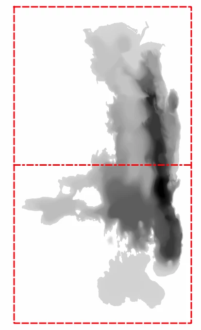
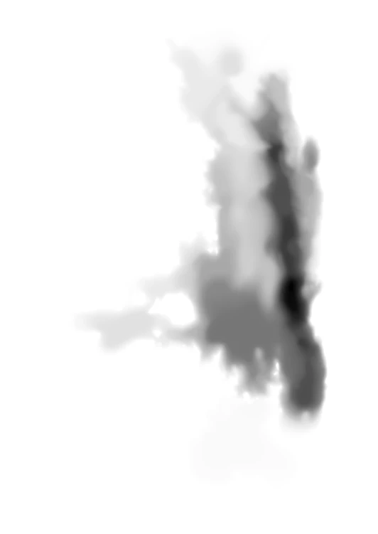
It produces a reasonable DEM output that I’m processing through QGIS with DEMto3D:
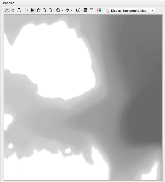
Banding from contours:
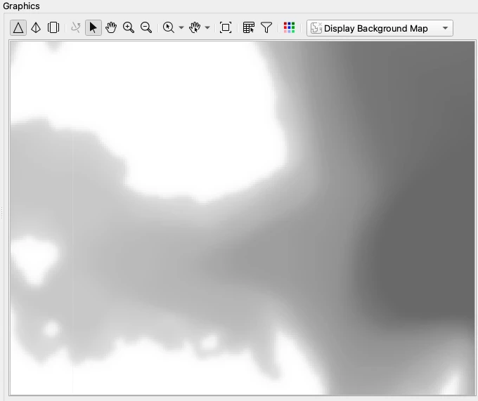
A closer look at the .stl shows hard contour line edges instead of smoother transitions:
I’ve read some about using PointCloudCombiner and NumericRasterizer, but don’t know if that will address this situation. I also tried a workflow with NumericRasterizer, but the results were similar. In the past I’ve tried gaussian filters, or other smoothing techniques, but that really disrupts the shorelines. Feedback is appreciated.
Best answer by artie
I went back to my original model, put on my thinkin’ cap, added/tweaked some new transforms and ended up with something that is mostly right.
Project Challenges
A 40km bathyscape that has very shallow/sparse contours (10m deep over thousands of meters) over large areas plus much deeper (100+ meters deep smaller areas) and tight contours that were glacier carved
The original shapefile had mixed vector types that I couldn’t sort out in QGIS, so I needed to apply Snappers/AreaBuilders to sort that out
The widely spaced contours created a hard edge with the RasterDemGenerator, so I needed to pre-process the lakebed with a coarse surface modeler and then a fine RasterDemGenerator to smooth out the contour line edges. For land I used a separate fine RasterDEMGenerator
I needed sharp shorelines for both the surrounding land mass and the many islands. For this I used a number of clippers, and RasterMosaickers, but that introduced more complexities dealing with the alpha channels and differing palettes
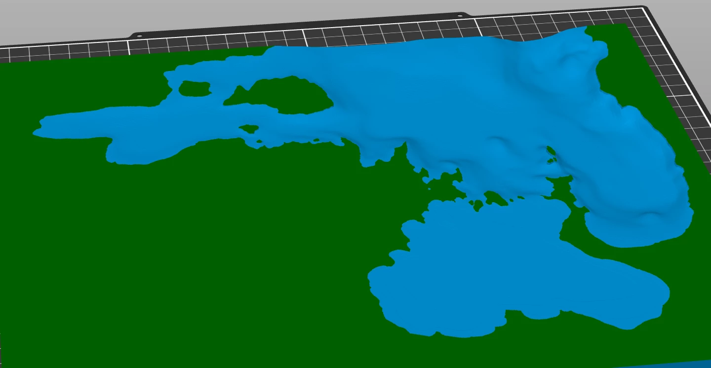
The clippers created a raggy shoreline edge that I might working on tweaking before final print, maybe reducing the RasterDemGenerator from 2 to 1, but that will add a lot of time.
The land area needed to be flat to make applying a secondary filament color easier.
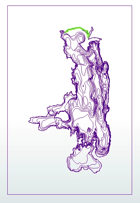
I attached screenshots of the original shapfile contours, the eventual workflow, the DEM Raster and the lower half of the .stl as it appears in PrusaSlicer. I haven’t printed it yet, as it takes 24+ hours to print with .1 layers for smoothness, but based upon my prior dozen trials I’m feeling better. Hope these experiences may help others. FME has been great compared with the slogging I did with GRASS/QGIS/SAGA/etc.
Just an idea: if you are looking to smooth the data but keep the shoreline detailed can you create a workflow that isolates your shoreline from processing or add your zero line (shoreline) back into the data after smoothing the data? Merge/update raster values along that shoreline area?
Thanks for your feedback, I’ll develop a workflow to try that.
I inserted an AttributeFilter (filtered to just lakebed, not shoreline) and inserted a RasterConvolver after the RasterDEMGenerator. Although there is smoothing happening, the 11x11 grid doesn’t cover enough area to smooth out the larger scale contour changes (just the edges).
One other idea I was exploring is whether there is a way to generate intermediate points between contour lines?
For instance, one contour line might be 20m and the next is 40m, but they are separated by thousands of meters. Wondering if I can convert the shapefile vectors to raster points and then generate something like point clouds between the contour points? That would smooth out contour to contour ‘steps’. The challenge would be to generate the points just between neighboring contours (one to one) and not against all (one to many). Is this possible with FME?
One other idea I was exploring is whether there is a way to generate intermediate points between contour lines?
For instance, one contour line might be 20m and the next is 40m, but they are separated by thousands of meters. Wondering if I can convert the shapefile vectors to raster points and then generate something like point clouds between the contour points? That would smooth out contour to contour ‘steps’. The challenge would be to generate the points just between neighboring contours (one to one) and not against all (one to many). Is this possible with FME?
This is, in broad terms, what the RasterDEMGenerator (and other surface modelling transformers) do.
I wonder what the band defnition is, the RasterDEMGenerator outputs it as Real64 by default, which should prevent banding, but maybe somewhere in the process it gets reinterpreted?
My challenge with bathys (GRASS, QGIS, SAGA) and now FME is the shapefile vector contours are 10 to 20m, but in a bathyscape the these contour lines can be miles apart. The result is a sharp edge with most rasterizers.
To try and get around this, with FME, my latest workflow runs the bathy contours through SurfaceModeler first (at a coarse resolution to minimize sharp contour transitions, 100x100) and then run that through RasterConvolver and then RasterDEMGenerator at a fine resolution (2x2). The end result of this is much more gradual contour progressions. However, it also dramatically and negatively impacts the shoreline. To try and address this I process the shoreline outwards with RasterDEMGenerator at 2x2 resolution. Then I run Clipper on both to retain the sharp shoreline out for land and shoreline in for the lakebed and assign 0 for nodata (transparent). What I’m trying to do no is RasterMosaicker them together as an overlay. I’m dealing with RasterMosaicker errors related to banding, but both inputs have only 1 band. Working on palettes to see if that is the problem. An additional wrinkle I had to work through with Clipper on the lakebed is dealing with Islands. That required another clipper. Here’s my workflow so far (feel free to comment and tear it apart, I’ve only been using FME for a couple of hours):
Unfortunately, triangulation is not well suited to creating DEM from contour lines. However, FME also includes the RCaller, giving you access to more powerful statistical methods of generating the DEM.
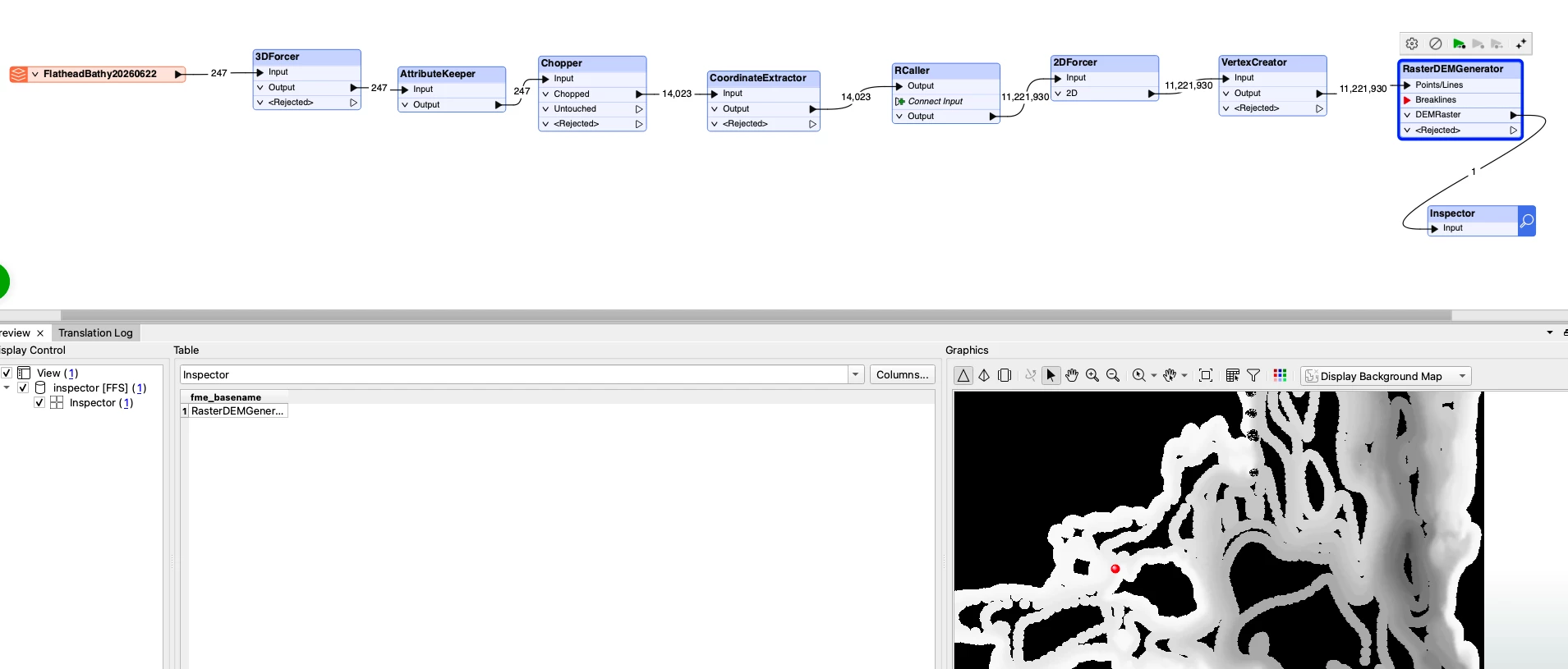
After your 3DForcer, use a Chopper with vertices set to 1 to convert the contour lines to points, then send the resulting points to an RCaller. Open the RCaller parameters and ensure your libraries (e.g., sp, raster, and an interpolation package like gstat) are installed in your R environment.
My R skills are quite poor, so I asked Gemini for a useful script to create the DEM, with these results:
1. The FME RCaller Transformer
Connect an RCaller transformer to the output of your coordinate-extracted stream.
In the RCaller parameters, define the input data frame (e.g., contours) to include your _x, _y, and _z attributes.
2. R Script with gstat
In the R Script window, write the following script. This calculates the variogram and uses Ordinary Kriging to map the predicted elevation points over your desired grid. Make sure the gstat and sp libraries are installed in your R environment:
# Convert to SpatialPointsDataFrame coordinates(data) <- ~_x+_y
# Create an empty grid for DEM interpolation (example uses 10m x 10m cell size) # You can adjust x and y boundaries dynamically based on your data extent x.range <- as.integer(range(data@coords[,1])) y.range <- as.integer(range(data@coords[,2])) grd <- expand.grid( _x = seq(from = x.range[1], to = x.range[2], by = 10), _y = seq(from = y.range[1], to = y.range[2], by = 10) ) coordinates(grd) <- ~_x+_y gridded(grd) <- TRUE
# Calculate variogram and perform Kriging # Note: You can customize the variogram model (e.g., model="Sph") var.model <- variogram(_z ~ 1, data) var.fit <- fit.variogram(var.model, vgm(model="Sph")) kriging.result <- krige(_z ~ 1, data, grd, model=var.fit)
# Prepare output back to FME with X, Y coordinates and the predicted Z value fmeOutput <- data.frame( _x = coordinates(kriging.result)[,1], _y = coordinates(kriging.result)[,2], _elevation = kriging.result$var1.pred )
3. Reconstructing the DEM Raster in FME
Place a 2DForcer after the RCaller to flatten the points output by R.
Attach a VertexCreator (or 2DPointReplacer) using the _x and _y attributes from the fmeOutput.
Route these processed points into a NumericRasterizer or RasterDEMGenerator transformer to convert the scattered interpolated points into a continuous raster format.
Yow, hadn’t wanted to dive that deep into esoteric processing. I’ll give it a try, but RCaller is brand new to me so I don’t know of my success rate. See next post for my findings.
Whew, what a rabbit hole. I’ve only been using FME a couple of days and R for one day, so a very deep dive into R. I found there were a number of other requirements to get all of this running on MacOS:
I needed to install XQuartz
I needed to install a number of additional libs (in addition to your recommended) to get everything to run, but I failed to note them (just ran, got the error, installed the lib). I found it easier to use the R Gui package installer and check the ‘install dependencies’ option.
I had to create a user library for FME R: mkdir -p ~/Library/R/$(uname -m)/$(R --version | head -1 | grep -oP '\d+\.\d+')/library
I had to set up a path in ~/.Renviron of: R_LIBS_USER=/Library/Frameworks/R.framework/Versions/4.6/Resources/library
I had to update the path to Rscript in FME Options to: /Library/Frameworks/R.framework/Versions/4.6/Resources/Rscript
I replaced all the ‘_x/y/z’ vars in your script with the updated var names
I’ll continue to update this post with additional challenges I find, but the script has been running for appx 2 hours, so assume I’m moving in a forward direction.
Kriging can be very slow, but it can be sped up by setting the nmax and maxdist parameters on the krige operation.
Alternatively, you could use Inverse Distance Weighting instead of Kriging:
idw_results <- idw(
  formula = z ~ 1,      # Variable 'z' to interpolate
  locations = my_points,# Spatial points data (sf or sp format)
  newdata = my_grid     # Grid or points to be predicted
)
where nmax is the maximum number of points to use in setting the cell value, and maxdist is the radius of a circle containing roughly the nmax number of points in the sparsest location.
I’m getting a little closer. I changed the chopper value from 1 to 7 to test speeding it up, which it did. However this created areas with no points (where contours are very far apart, see attached screenshot). I tried a chopper of 6 but there are still areas with no points. To fix this do I make the maxdist larger? Or, other suggestions?
Instead of changing the Chopper setting, add a Generalizer before it to simplify the contours. Use the Thin algorithm and set the minimum distance between points.
@daveatsafe , when I had chopper set to 1 the output was 56k points, which seemed to overwhelm RCaller, even with the nmax/maxdist attributes. Right now, with a generalizer and chopper of 5 I’m getting 17k points from chopper to RCaller. Is there a max number of points I should consider to help the process complete in a reasonable time frame? I tried to implement the BLAS libraries solution, but they’e no longer available in MacOS Tahoe at the OS level (via symbolic link.) I appreciate the advice!
After making more tweaks to the generalizer, chopper and RCaller settings I’m sort of getting back to some of original problems. When I change parameters to deal with the long distances between bathy contour lines, to smooth out the sharp breaks, I end up smoothing the shoreline too much. In the initial incarnations I tried to deal with this by splitting the .stl to create a sharp shoreline, but it was highly inaccurate given the topology changes and the inclusion of islands. I’ll continue tweaking the RCaller process, but I’m thinking it may not be a better solution overall (bathy contours versus shorelines versus islands.)
Once you get a nicely distributed point set, use the shoreline to clip all the points out of the lake with a Clipper transformer. Then send the remaining points to the Points input of a SurfaceModeller, and the Shoreline to the Breaklines input. The TINSurface output will give you a nice mesh with a defined lake boundary, flat lake and nicely generalized surface outside.
This gives you the top of the STL. To add the bottom and sides, use a GeometryCoercer to coerce the mesh to fme_composite_surface, then use an Extruder to do a Vertical Extrude by a negative value larger than the height of the surface. This will give you a solid with the bottom surface following the top, which is likely not what you want to model.
To trim the bottom flat, add a second connection from the TINSurface output of the SurfaceModeller to a BoundingBoxReplacer, then connect that output to Bufferer with a buffer distance of 1 and buffer type of Area (2D). Connect the Buffered output to a 3DForcer with elevation set to the elevation that you want to use as the bottom of the model. Finally connect to an Extruder for a Vertical extrude to -100000.
Add a Clipper transformer, then connect the extruded surface to the Clippee input and the extruded boundary to the Clipper input. This will clip the bottom off of the extruded surface to make it flat. Connect the Outside output to the STL writer.
I went back to my original model, put on my thinkin’ cap, added/tweaked some new transforms and ended up with something that is mostly right.
Project Challenges
A 40km bathyscape that has very shallow/sparse contours (10m deep over thousands of meters) over large areas plus much deeper (100+ meters deep smaller areas) and tight contours that were glacier carved
The original shapefile had mixed vector types that I couldn’t sort out in QGIS, so I needed to apply Snappers/AreaBuilders to sort that out
The widely spaced contours created a hard edge with the RasterDemGenerator, so I needed to pre-process the lakebed with a coarse surface modeler and then a fine RasterDemGenerator to smooth out the contour line edges. For land I used a separate fine RasterDEMGenerator
I needed sharp shorelines for both the surrounding land mass and the many islands. For this I used a number of clippers, and RasterMosaickers, but that introduced more complexities dealing with the alpha channels and differing palettes
The clippers created a raggy shoreline edge that I might working on tweaking before final print, maybe reducing the RasterDemGenerator from 2 to 1, but that will add a lot of time.
The land area needed to be flat to make applying a secondary filament color easier.
I attached screenshots of the original shapfile contours, the eventual workflow, the DEM Raster and the lower half of the .stl as it appears in PrusaSlicer. I haven’t printed it yet, as it takes 24+ hours to print with .1 layers for smoothness, but based upon my prior dozen trials I’m feeling better. Hope these experiences may help others. FME has been great compared with the slogging I did with GRASS/QGIS/SAGA/etc.