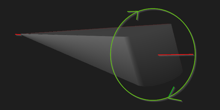
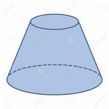
I think that the attached diagram will help solve your question )
Hi @muzhnasto, I'm still confused with this problem!
I've tried to apply your logic to my data but it still doesn't quite work as expected. See screenshot.
I've attached sample data and the updated workspace. How can I make it work so that each of the extruded features will rotate around its own axis?
The problem is that you are trying to rotate a 2D buffer by a 3d axis.
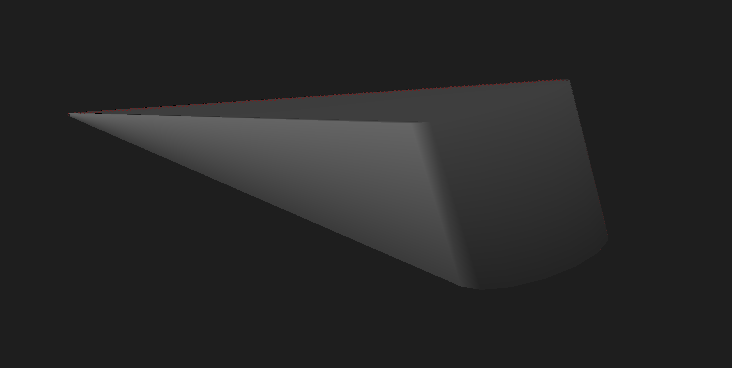
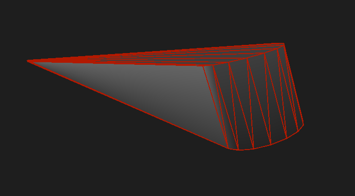
The buffer that you extrude has "coordinates" xS,yS,0 and xE,yE,0. So, by rotating that along a 3D axis, the rotation goes along a cone trunk with the 3D axis as its axis. (I just like writing "axis" 😁)
You have to rethink this from the very begining.
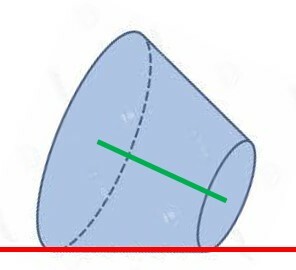
I can think about a few workarounds. One would be creating a rectangle on the starting vertex, 3DRotate it to get it perpendicular to the line and extrude in the direction of the line, OR create offsets of the line, create surfaces from the offsets and then construct a solid from them.
Hi @muzhnasto, I'm still confused with this problem!
I've tried to apply your logic to my data but it still doesn't quite work as expected. See screenshot.
I've attached sample data and the updated workspace. How can I make it work so that each of the extruded features will rotate around its own axis?
Hi @caracadrian
Thanks for your response. I don't quite understand though what you are saying. My input polygon has 3D coordinates so I assumed a 3D rotation shouldn't be an issue. The thing I am struggling with is the definition of the vector that defines the axis. I believe I shouldn't need to use a workaround as that's what the 3DRotator is there for.
The tricky bit is to define the axis relative to the extruded polygon. Unfortunately, the FME help page doesn't have a diagram that could help understand the logic.
Hi @muzhnasto, I'm still confused with this problem!
I've tried to apply your logic to my data but it still doesn't quite work as expected. See screenshot.
I've attached sample data and the updated workspace. How can I make it work so that each of the extruded features will rotate around its own axis?
The Bufferer output is 2D. That is the problem.In the picture above the green line represents your 3Dline, the red line represents the buffer you created with the Z coordinates 0, and the faces of the cone represent the possible outputs of the 3DRotator for your workflow.
When you buffer, the output doesn't stay in place (as in 3D) and that is causing the weird output.
Hi @muzhnasto, I'm still confused with this problem!
I've tried to apply your logic to my data but it still doesn't quite work as expected. See screenshot.
I've attached sample data and the updated workspace. How can I make it work so that each of the extruded features will rotate around its own axis?
Hi @caracadrian
Apologies if my initial description of the workflow wasn't detailed enough. I'm aware that the Bufferer creates a 2D polygon output but I do convert that back to a 3D polygon through an additional process which I omitted in my description to not confuse things too much. If you take a look at my input data and workspace posted above (3D_rotate.zip) you'll see that I am dealing with a 3D polygon.
I've played with the 3DRotator parameters a bit and I'm able to adjust the custom axis to get closer to the desired outcome. I'm also able to create a 3D line defining the axis of my object.
The question is - how can I convert my 3D line (object axis) into the required axis parameters (vector) so that the rotation will be exactly right?
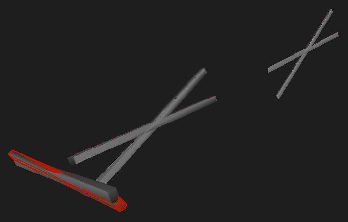
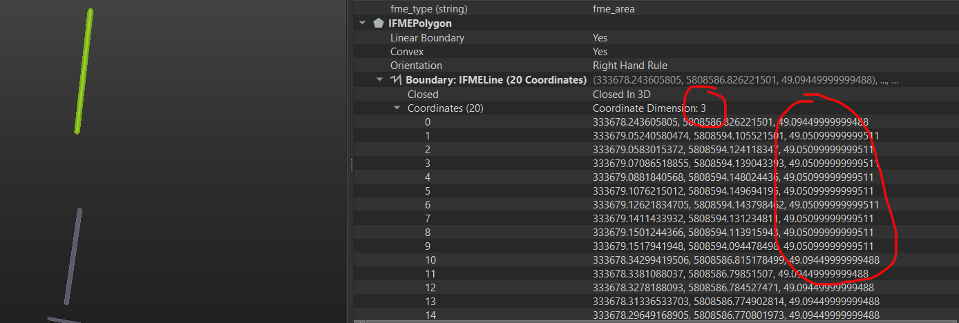
Here's a snip of my input polygon data: