Question

Polygons (trapezoids) from lines


j_geo
Participant
Forum|alt.badge.img+1
  • Participant

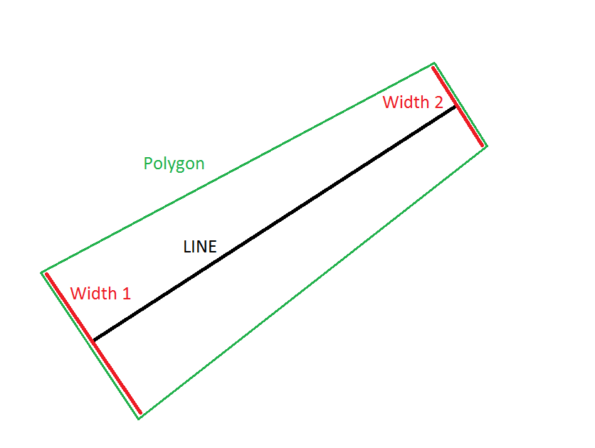
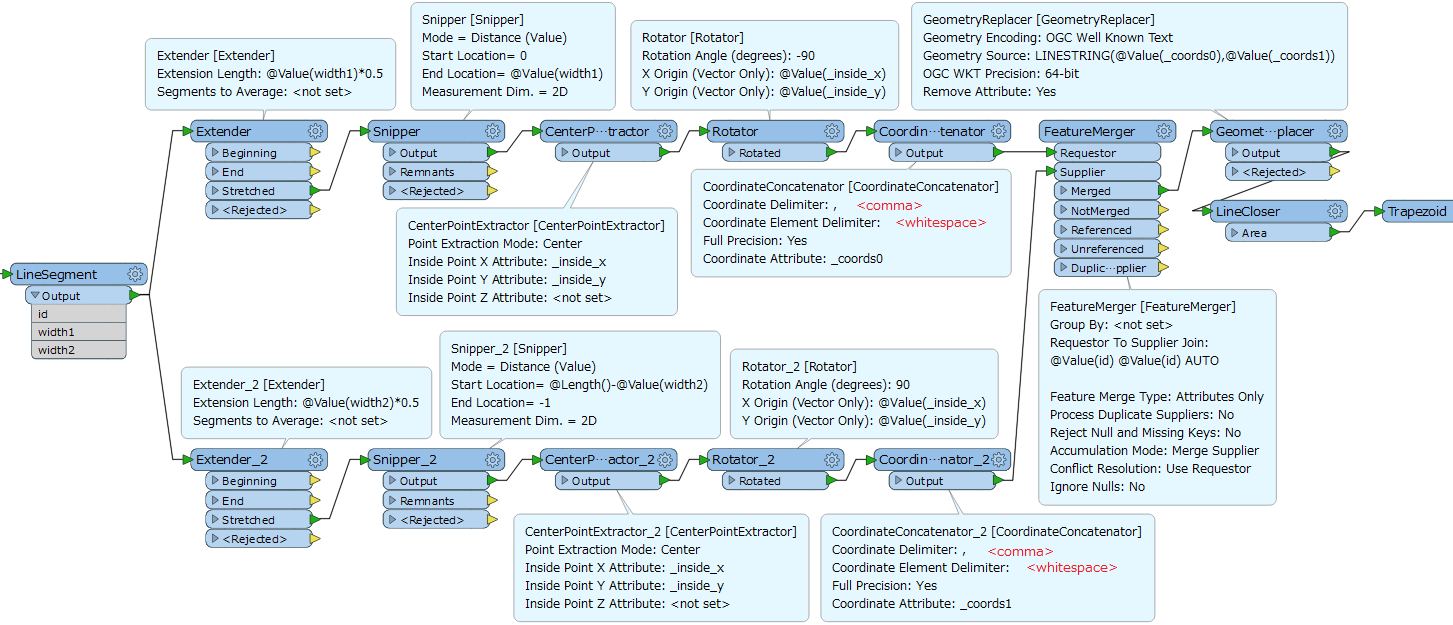
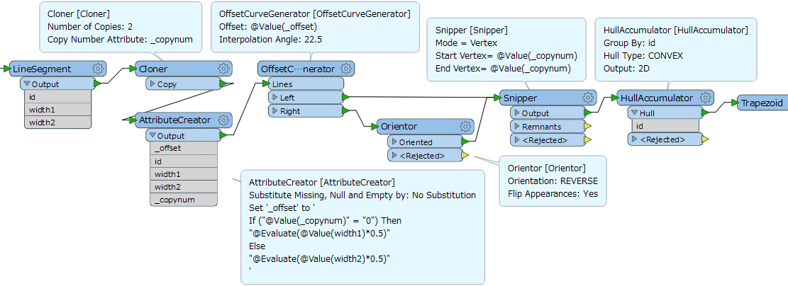
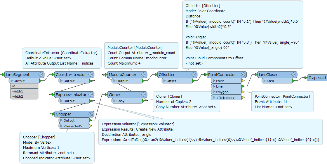
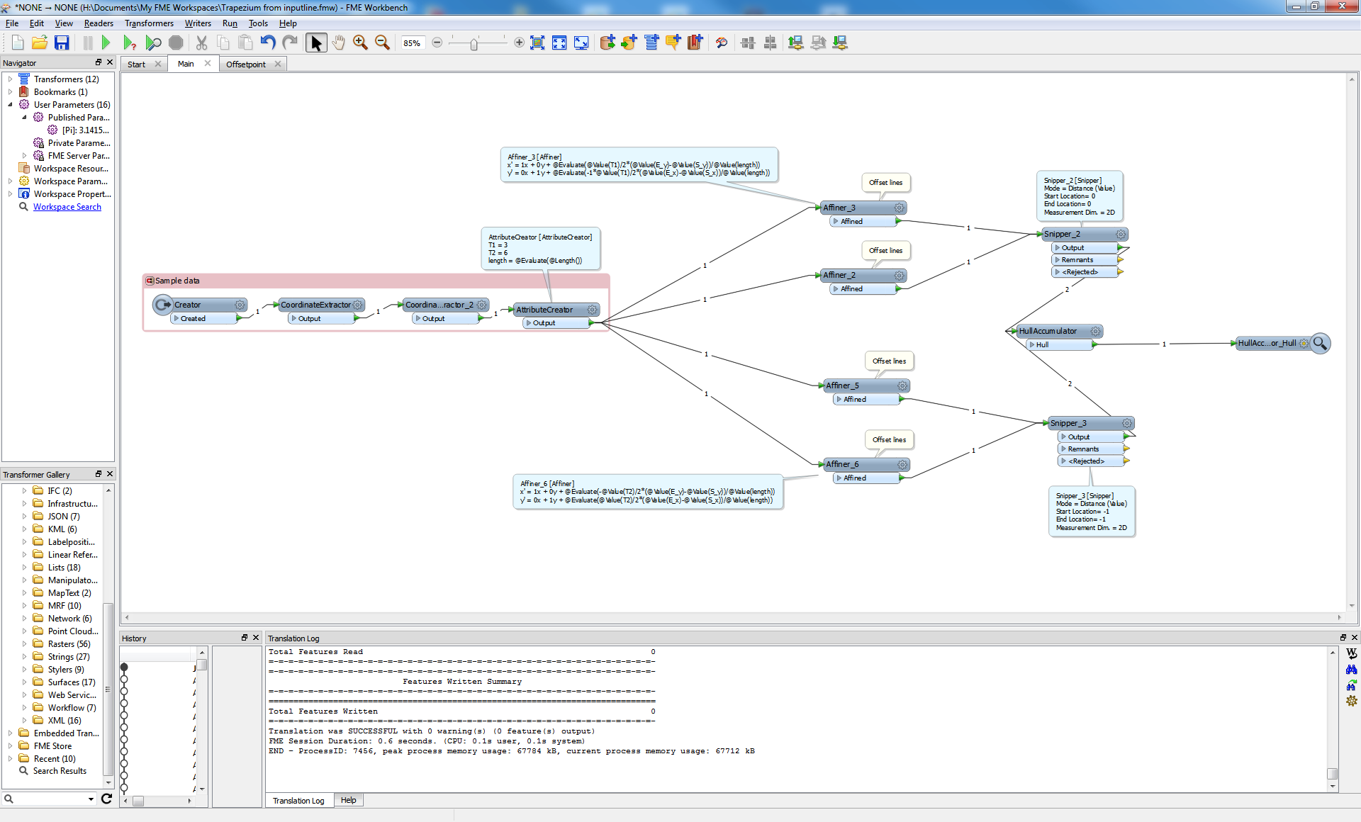
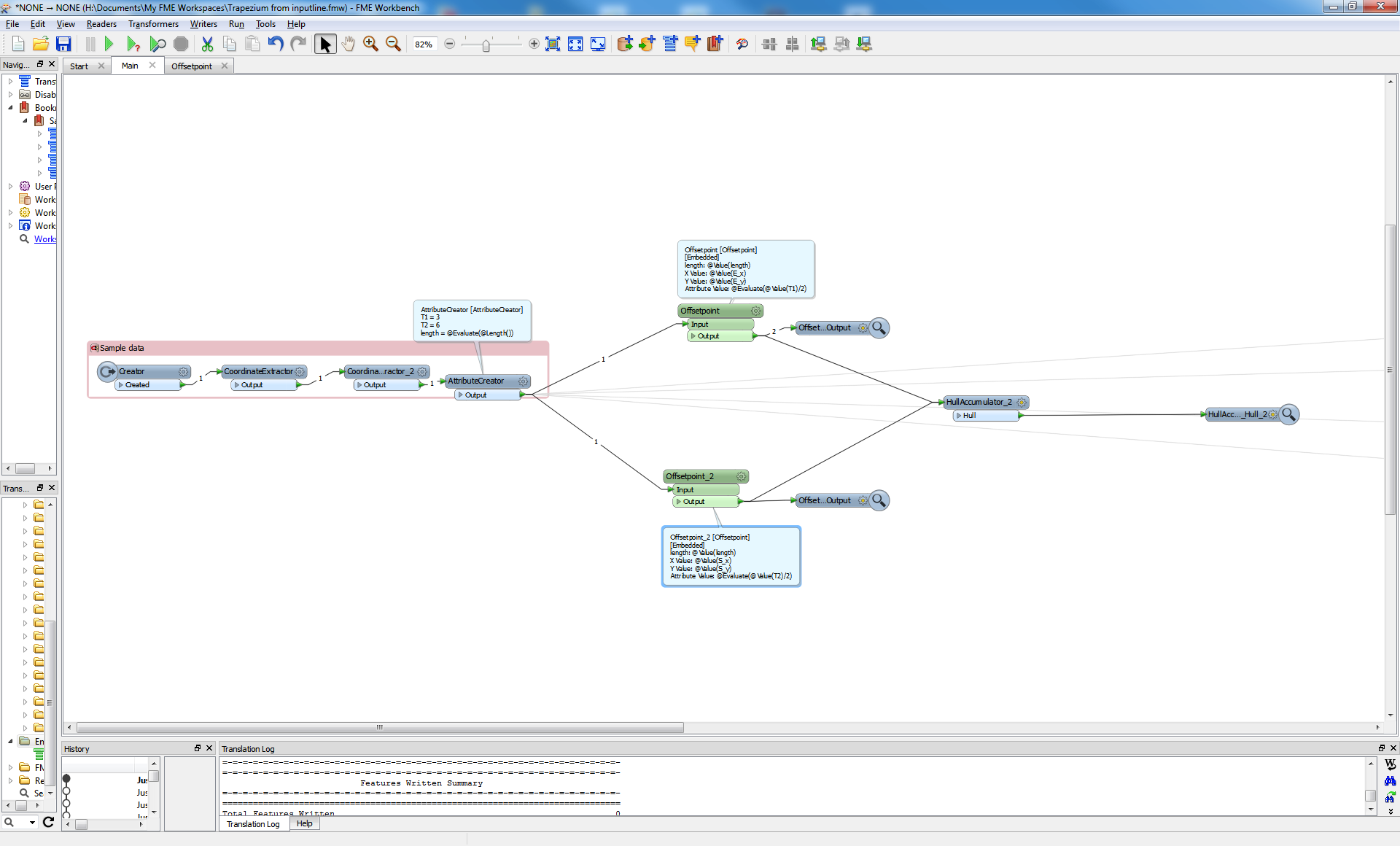
I want to make polygon (trapezoid) from each line segment that has information about trapezoid width at start and at the end.

Is it possible with FME?

12 replies

takashi
Contributor
Forum|alt.badge.img+19
  • Contributor
  • March 17, 2016

Hi @jernejtekavec, I guess that the line segment should be the base of the required trapezoid. Is it right? Then, not sure what the given information means, sorry. Which parts of a trapezoid does the "width at start and at the end" indicate? If you could illustrate contents of the given information using an image, it would help us to understand your requirement exactly.


j_geo
Participant
Forum|alt.badge.img+1
  • Author
  • Participant
  • March 17, 2016

Hello,

now when I read my question again, I see that I really made it confusing.

I attached a picture that will, I hope, help to understand what I'm trying to do


takashi
Contributor
Forum|alt.badge.img+19
  • Contributor
  • March 17, 2016

@jernejtekavec, I got it. This procedure might be a solution, applying 2D vector operations.

1. Extract start node coordinates (x0, y0) with the CoordinateExtractor.

2. Extract end node coordinates (x1, y1) with the CoordinateExtractor.

3. Calculate the length of the line segment.

4. Calculate the unit vector along the line.

ux = (x1 - x0) / length; uy = (y1 - y0) / length

5. Replace the line with the 1st vertex of the trapezoid (VertexCreator, Replace with Point mode).

X = x0 - uy * width1 * 0.5; Y = y0 + ux * width1 * 0.5

6. Add the 2nd vertex (VertexCreator, Add Point mode)

X = x0 + uy * width1 * 0.5; Y = y0 - ux * width1 * 0.5

7. Add the 3rd vertex (VertexCreator, Add Point mode)

X = x1 + uy * width2 * 0.5; Y = y1 - ux * width2 * 0.5

8. Add the 4th vertex (VertexCreator, Add Point mode)

X = x1 - uy * width2 * 0.5; Y = y1 + ux * width2 * 0.5

9. Finally transform the resulting line into a polygon with the LineCloser.

[Addition] This screenshot illustrates the workflow on the Canvas.

[Addition 2] This is another implementation of the vector operations with FME 2016. Note: in FME 2016, you can extract all coordinates as a list attribute by the CoordinateExtractor, and use an attribute value newly created in an AttributeCreator to construct other attribute values in the same AttributeCreator.


pratap
Contributor
Forum|alt.badge.img+11
  • Contributor
  • March 17, 2016

Hi,

Alternate approach, If I understood your required. line2polygon.fmw


mark2atsafe
Safer
Forum|alt.badge.img+43
  • Safer
  • March 17, 2016

Another version. Mine uses the 2DArcReplacer on each end point and then picks up the start/end point of each arc and joins them all together.

trapezoidreplacer.fmw


takashi
Contributor
Forum|alt.badge.img+19
  • Contributor
  • March 18, 2016

Interesting. There is more than one way, almost always :-)

0684Q00000ArLTcQAN.png

You can also use a HullAccumulator to create the trapezoid, by connecting it to the Rotators in the above workflow.

Then, Python version for the 2D vector operation approach.

# PythonCaller Script Example
# Replace a line segment with a trapezoid polygon.
# Assuming that the input feature has a single line segment geometry.
import fmeobjects, math

def replaceLineSegmentWithTrapezoid(feature):
    # Get coordinates of the start and end nodes.
    coords = feature.getAllCoordinates()
    x0, y0 , x1, y1 = coords[0][0], coords[0][1], coords[1][0], coords[1][1]
    
    # Compute the unit vector along the original line segment
    len = math.hypot(x1 - x0, y1 - y0)
    ux, uy = (x1 - x0) / len, (y1 - y0) / len
    
    # Create a line that represents the boundary of required trapezoid.
    w1 = float(feature.getAttribute('width1')) * 0.5
    w2 = float(feature.getAttribute('width2')) * 0.5
    if feature.getDimension() == fmeobjects.FME_TWO_D: # 2D
        coords = [(x0 - uy * w1, y0 + ux * w1),  (x0 + uy * w1, y0 - ux * w1), \
            (x1 + uy * w2, y1 - ux * w2),  (x1 - uy * w2, y1 + ux * w2)]
    else: # 3D
        z0, z1 = coords[0][2], coords[1][2]
        coords = [(x0 - uy * w1, y0 + ux * w1, z0),  (x0 + uy * w1, y0 - ux * w1, z0), \
            (x1 + uy * w2, y1 - ux * w2, z1),  (x1 - uy * w2, y1 + ux * w2, z1)]
    boundary = fmeobjects.FMELine(coords) # create a line from 4 vertices.
    boundary.appendPoint(coords[0]) # close the line.
    
    # Replace geometry of the input feature with a trapezoid polygon.
    feature.setGeometry(fmeobjects.FMEPolygon(boundary))

mark2atsafe
Safer
Forum|alt.badge.img+43
  • Safer
  • March 18, 2016

Just a thought, but I suspect the main problem you might find in all these solutions - including mine - is that we tested against a single line. Once you get multiple lines involved you'll need to look at giving them an ID and setting some group-by parameters.


gio
Contributor
Forum|alt.badge.img+15
  • Contributor
  • March 18, 2016

lot of lines...

Just offset the centrepoint of each line by half the width to each side.

Then hullaccumulate it.


fmelizard
Contributor
Forum|alt.badge.img+17
  • Contributor
  • March 19, 2016

Wow, I'm impressed. Many many cool ways to skin the cat. I leave it to @jernejtekavec to pick the one he likes best as the "best answer". I love them all!


takashi
Contributor
Forum|alt.badge.img+19
  • Contributor
  • March 19, 2016

Yes, many ways. I have six ways so far. This is the latest one:

I noticed that math expressions cannot be evaluated in the conditional value setting for the OffsetCurveGenerator's Offset parameter. The AttributeCreator is a meantime workaround.

It would be better if the HullAccumulator had "Input is Ordered by Group" option, for similar scenarios to this question.

[Addition] The tenth. Tried the new "Polar Coordinate" mode for the Offsetter of FME 2016.


gio
Contributor
Forum|alt.badge.img+15
  • Contributor
  • March 21, 2016

@jernejtekavec

Less is better...

..right part is all it takes.

Affiners are same, could be stuffed in a custom. (i was too lazy to do that now).

So 3 transformers is enough...


gio
Contributor
Forum|alt.badge.img+15
  • Contributor
  • March 21, 2016

as i was playing anyway..

here is with pointoffset..lowfootprint

Use azimuth for the angle (or your own one-liner..;))

Cookie policy

We use cookies to enhance and personalize your experience. If you accept you agree to our full cookie policy. Learn more about our cookies.

 
Cookie settings