The issue I'm having is I have several CAD "Markers" in my dataset im converting to GIS. These markers are all different and include Sand Marker, Orchard Marker, Rice Paddy Marker, etc. I need to extract a point from the center of these markers/ somewhere near the center of these markers. Is there a transformer/ easy process that does this or will it need to be on a case by case bases. Some markers have touching lines, some do not, some are a bunch of circles. Below are some examples of what these look like.
Rice Paddy Marker
Field Marker

Sand Marker

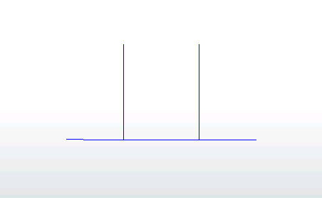
Marsh Marker

For the first two I know I can extract the line with the longest length and place a center point. But for the others the "length" parameter wont work.
Also, there are no attributes that can be used for extraction of a point across all of the data sheets. Each sheet has different attributes for the lines I would like to use. So an attribute would work on a sheet level basis but that attribute changes as the sheet changes.