Hello FME Community,

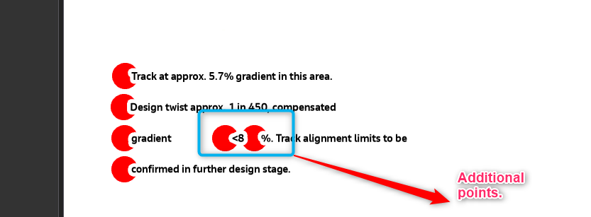
I am trying to convert annotations from a CAD (.DWG) file to a GIS (.GDB) file in the form of points, in such a way that each line of annotation text is a separate point with an attribute of this text. Everything seems to work fine in my workbench, however, after attaching to GIS programming and loading the resulting points, it turns out that in many cases additional points have been created in each line of text, which prevents me from using them correctly.
Has anyone encountered something like this and would be able to help.

I attach screenshots of sample annotations in AutoCAD and after conversion in GIS software.
FME version: FME(R) 2023.2.1.0 (20240104 - Build 23774 - WIN64) 


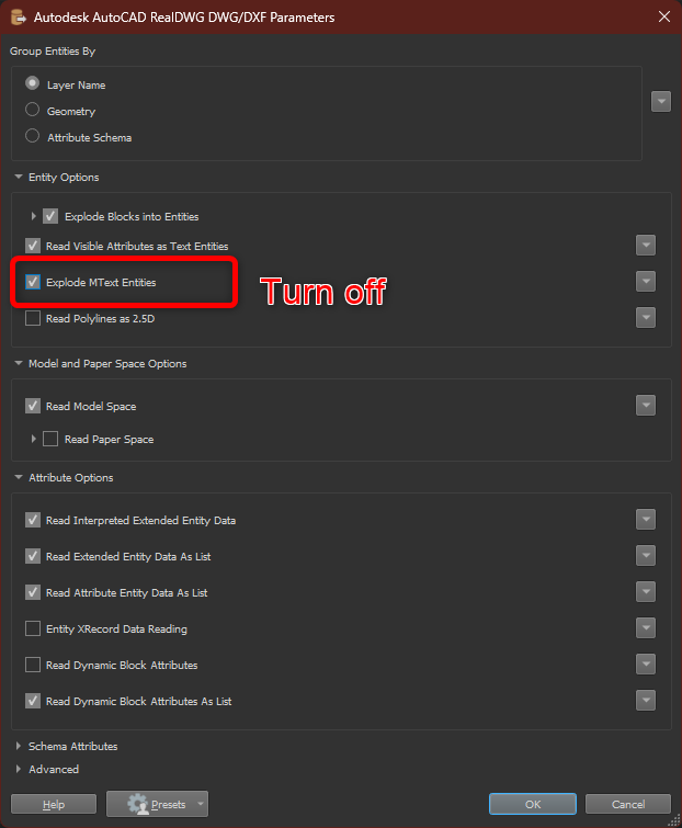
Hey I have had this problem quite some time ago, it has something to do with how you set up your reader. There is a parameter called "Explode MText Entities”, if you turn this off it will read the whole MText as 1 line with 1 point. Then you can probably style your labels in your GIS software to look the way you want.


Hi, birgit, thanks so much for your answer, unfortunately I had it turn off before, and it makes my annotation look very bad as those overlaps with other annotations and other parts of design. For me, it would be best if I had just 1 point per annotation line in cad. There is no way in GIS to split those annotations into multiple lines, so I have sometimes one very long annotation with like 50 words. Do you or anyone else know if it is possible? 


I created an example workspace for you. I didn't have any Mtext objects near so I just created some example data. You might need to tweak it a little bit to get it to work for you but it does demonstrate a way to combine the text rows


Reply