Hey FME team,

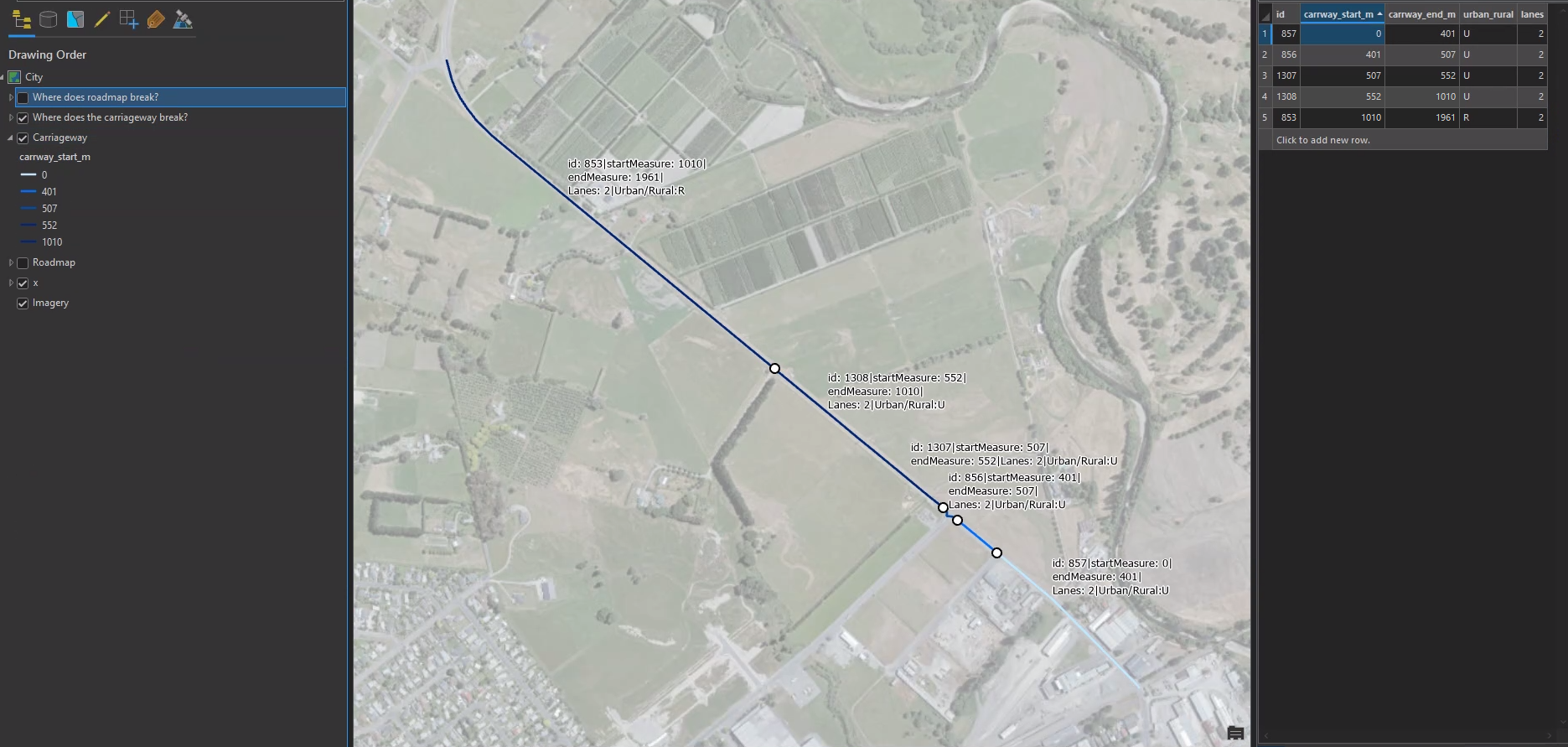
My coworkers and I are trying to figure out a tough polyline overlay issue. We are building a routable transport network for a city. We received 2 polyline datasets for the city’s road network. One dataset (Roadmap) contains geometry that we are licensed to modify the geometry for (as the original data were poorly connected and incomplete), and the second dataset (Carriageway) contains geometry that we are not able to use for the transport network but can use attributes for. Attributes include the number of lanes, whether the centrelines is in a urban or rural location, and the start and end measures for the carriageway feature. The link between the two polyline layers is a field called road_id, which forms a many:many relationship between the map layer and the carriageway. An example is shown below (3 Roadmap features, 5 Carriageway features):
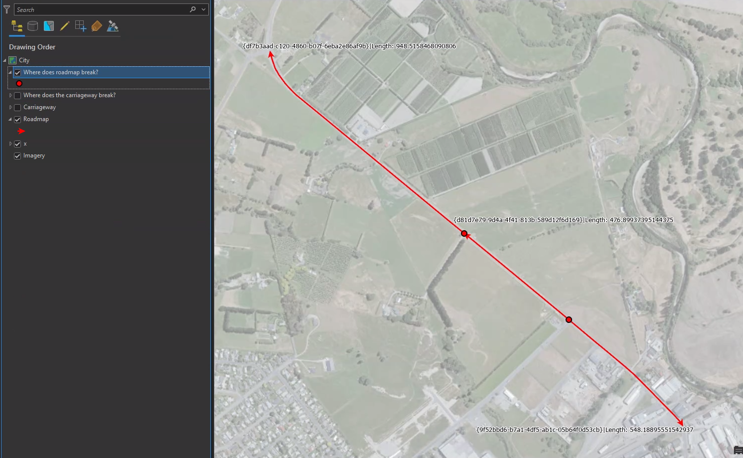
Roadmap (modified, x3)
Carriageway (x5)

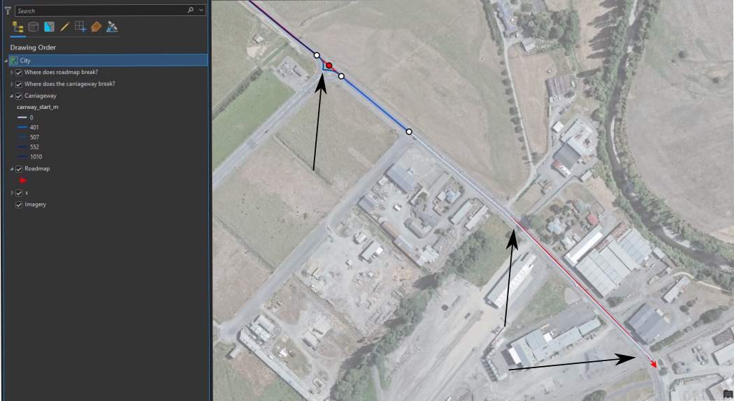
Our issue is there is a slight offset between the modified Roadmap geometry and the Carriageway Geometry, so there is not a perfect overlay of the two layers in most cases:


The desired outcome is the 3 Roadmap geometry features, and a related table for the lanes attributes and urban rural attributes split according to the geometry of the Roadmap geometry features to account for the modified geometry e.g.
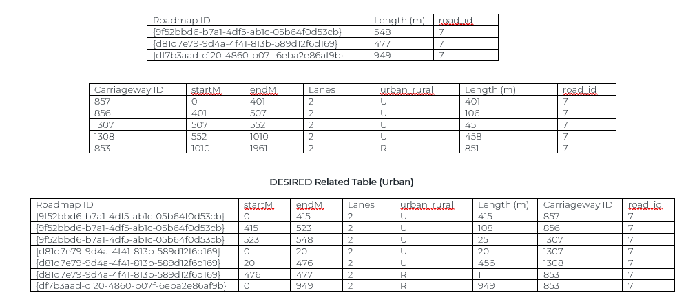
Essentially, the 3 Roadmap records have been split according to where the Carriageway features end. These endpoints lie at variable distances along the Roadmap records which is why you get 1m long segments of Rural in the Desired table. Note that the modified Roadmap geometries mean that they extend beyond the length of the Carriageway records.

We’ve tried:

  1. Converting the Carriageway lines into vertices (“CoordinateExtractor”, start and end & “VertexCreator”)
  2. “Snapper” on the vertices so that any misalignment between starts and ends are corrected
  3. “AnchoredSnapper” to the RoadMap layer
  4. PointOnLineOverlay to break the Roadmap wherever the vertices overly the Roadmap.

We can’t replicate the desired table so far though. We are also trying to replicate this for the entire city (not just one road). Thanks for your help in advance. We’re using FME 2022.2.1

A fundamental problem you will have with all solutions is that the Carriageway Chainage Length M Measure is not going to equal the RoadMap Length M Measure.

For Example, for Road_ID = 7, currently you have 3 Polylines that have a Total Length of 1,974 metres,  but the Carriageway data is for a total chainage of 1,961 metres, and it is more complicated still in that one of the highest relative errors between the Total M is in Eg. Carriageway ID 1307 which I suspect is where the Carriageway line curves across the T-intersection whereas in the Roadway Feature it just straight lines past the T-intersection leading to a significant difference in the segment lengths through this part of the Carriageway.

There are ways that you may have to think about “scaling” the M measures in the Carriageway Table.

However, to “align” them to at least get something that overlays directly and compare, would use:

  1. CoordinateExtractor + ListExploder + VertexCreator on the Carriageway lines to get them back to Vertex Points
  2. NeighborFinder (With Group By road_id) with Carriageway Vertices as Base Features and Roadway Lines as Candidate Features.   This will give the Nearest Roadway X, Y coordinates for every Carriageway Vertex.
  3. VertexCreator on the output of this in “Replace Point” mode that shifts the Carriage raw vertices to the each nearest X, Y location on the Roadway.
  4. LineBuilder (Group By Carriageway_ID) to dissolve the Vertices back to Carriageway lines that will be now roughly aligned with the Roadways
  5. ...or alternative to LineBuilder is to leave the snapped Carriageway Points as is and instead find out what Relative Distance they are from the start point of each related Roadway using LengthToPointCalculator.

As these new Carriageway Lines will not have the same length as the originals, and the Start and Stop Nodes may not even lie on the Start and Stop Nodes of the related Roadway, then some sort of scaling logic is then needed to convert the Original Carriageway M values to equivalent Roadway M values, but at least with the aligned lines will be able to build logic off that.


Reply