Hi @connor27
Yes, this is possible. As you say, it's a bit more complex, but shouldn't be too difficult.
Here's a short video I created demonstrating how to turn id,x,y,diameter,depth into a 3D structure.
http://screencast.com/t/ERr8BYQvux
The pipelines would be slightly more difficult, but still possible I think.
If you need more assistance then please do ask here, or contact the Safe support or sales team (safe.com/support or sales@safe.com). They'll be able to help you out with a more detailed demo of exactly what you require.
Hope this helps
Mark
Mark Ireland
Product Evangelist
Safe Software Inc.
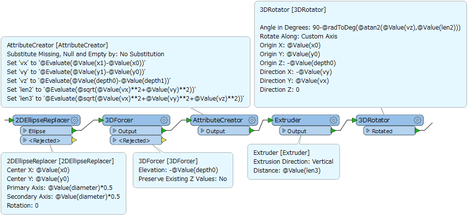
Hi @connor27, you can also create pipes with a similar way to the way @mark2catsafe suggested for manholes. Just add a process to rotate the cylinder-like solid. It requires some math expressions, but not so complex.
- 2DEllipseReplacer: Create a circle that represents the section of a pipe.
- 3DForcer: Give z-coordinate at the upstream node to the circle.
- AttributeCreator: Calculate 3D vector (upstream -> downstream) and 2D / 3D length of the pipe.
- Extruder: Extrude the circle vertically by the 3D length to form a cylinder-shape solid.
- 3DRotator: Rotate the solid in 3D so that it will lie between upstream and downstream.
Assuming that these attributes are given by the source dataset.
- Upstream coordinates and depth: x0, y0, depth0
- Downstream coordinates and depth: x1, y1, depth1
- Diameter of the pipe: diameter
Left: View in 2D, Right: View in 3D. Added a red center line to validate the result.
See also the attachment: create-pipe.fmw (FME 2016.1)
This would make a great transformer in the hub @takashi
In fact, the 3DBufferer can do that ;)
Hi @connor27
Yes, this is possible. As you say, it's a bit more complex, but shouldn't be too difficult.
Here's a short video I created demonstrating how to turn id,x,y,diameter,depth into a 3D structure.
http://screencast.com/t/ERr8BYQvux
The pipelines would be slightly more difficult, but still possible I think.
If you need more assistance then please do ask here, or contact the Safe support or sales team (safe.com/support or sales@safe.com). They'll be able to help you out with a more detailed demo of exactly what you require.
Hope this helps
Mark
Mark Ireland
Product Evangelist
Safe Software Inc.
Thank you very much Mark, the video helps greatly!
Connor
Hi @connor27, you can also create pipes with a similar way to the way @mark2catsafe suggested for manholes. Just add a process to rotate the cylinder-like solid. It requires some math expressions, but not so complex.
- 2DEllipseReplacer: Create a circle that represents the section of a pipe.
- 3DForcer: Give z-coordinate at the upstream node to the circle.
- AttributeCreator: Calculate 3D vector (upstream -> downstream) and 2D / 3D length of the pipe.
- Extruder: Extrude the circle vertically by the 3D length to form a cylinder-shape solid.
- 3DRotator: Rotate the solid in 3D so that it will lie between upstream and downstream.
Assuming that these attributes are given by the source dataset.
- Upstream coordinates and depth: x0, y0, depth0
- Downstream coordinates and depth: x1, y1, depth1
- Diameter of the pipe: diameter
Left: View in 2D, Right: View in 3D. Added a red center line to validate the result.
See also the attachment: create-pipe.fmw (FME 2016.1)
This is great Takashi, thank you very much for your reply!
Hi @connor27, I have a similar problem and I'm wondering if you could help get me started. I have CSV data sheets for block models for mining companies. The sheets include xyz (wsg 84 coordinates, or NAD 83), a metal grade for each block/point and a classification for each block (IE which resource category it fits into). Sometimes the sheets have other classification data such as whether or not it fits into an open pit, etc. We currently do this using C4D but it's a process that doesn't like large files and this process typically has large files As this something you could help with? I'll attach an example fo the data... thanks very much.
Here's an image of what one should look like:
block-model-example.jpg
And here's an example spreadsheet (not the same as the image):
https://drive.google.com/file/d/1_zAzNa5gi-uMkAkaqZ3zHXEhnKK2O8Ch/view?usp=sharing
Thanks for any assistance you can offer.