
I am converting Microstation DGN to AutoCAD DWG drawings. One thing I'm trying to translate exactly is the text insertion point and horizontal alignment. While the values come through exactly, visually, some of the text don't match. I have the following mapped:

  • igds_original_justification -> autocad_justification
  • igds_insertion_x -> autocad_alignment_x
  • igds_insertion_y -> autocad_alignment_y

And conditional values set for the following:

  • autocad_width_factor
  • autocad_shape_name

One thing I noticed is in Microstation, one can set both text height and text width. For DWG, the text width seems to assume the height (or size) value. See the attachment for the difference in the alignment:

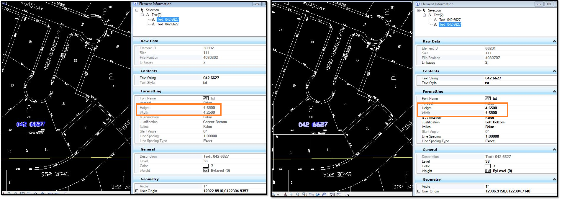
I'm hoping the alignment issue will be resolved if the width is the same as in DGN. Is it possible at all to set text width for DWG?

Is there any other way I can get the alignment to match perfectly?

Thank you.

Is this the format attribute you are looking for:

autocad_width_factorThe scaling applied in the x direction which makes the text wider or narrower. However, this doesn’t affect the weight (i.e., boldness) of the text string.

Range: 64-bit floating point number > 0 and <= 10000

Default: 1


Is this the format attribute you are looking for:

autocad_width_factorThe scaling applied in the x direction which makes the text wider or narrower. However, this doesn’t affect the weight (i.e., boldness) of the text string.

Range: 64-bit floating point number > 0 and <= 10000

Default: 1

No, it's not. That attribute is already applied for a different purpose. I'm looking for an autocad_text_width or autocad_width for text.


I understood that you want to match the text size in dgn and dwg. I did not understand your requirement... Can you share some screenshot (both from dgn and dwg) where you feel the difference.


I understood that you want to match the text size in dgn and dwg. I did not understand your requirement... Can you share some screenshot (both from dgn and dwg) where you feel the difference.

We probably need a repro (workspace, source data sample, template) to experiment with.


@lottegis could you please share some data and workspace with us? I wonder how off the texts are and how precise you need them to be.


I understood that you want to match the text size in dgn and dwg. I did not understand your requirement... Can you share some screenshot (both from dgn and dwg) where you feel the difference.

Here's some screenshots. Some of the text translate exactly, while you can see displacement in others.


We probably need a repro (workspace, source data sample, template) to experiment with.


@lottegis could you please share some data and workspace with us? I wonder how off the texts are and how precise you need them to be.


@LenaAtSafe Is it possible to verify if the AutoCAD parameters I listed are really all I can use to translate text?


So I wasn't able to to get the text width to be unique from text height and visually, there are still misalignments, but with these settings I settled with, the results are good enough:

  • autocad_width_factor -> igds_text_width_multiplier / igds_text_size
  • igds_original_justification -> use visual comparison to determine the best DWG justification, rather than following the Text justification charts
  • autocad_shape_name -> no change; conditional values mapping
  • igds_insertion_x -> autocad_alignment_x
  • igds_insertion_y -> autocad_alignment_y
Thanks for sharing good advice


Guessing you need to manipulate the text spacing.

It's a font property Apperantly hold by

TSPACETYE and TSPACEFAC (for Mtext at least) Which can't be set by fme (afaik)

For single line text (text object) there appear to be no control as I understand it)

But you can control it somewhat using "autocad_width_factor" (not same as spacing tough)


Reply