I have the some features and its coordinates in excel file and have an XML with the same features. I need to update the coordinates from excel to XML. Please suggest me the transformers and the process to update the geometry coordinates from excel to XML. I have point and linear features also. Please suggest. Thanks in advance.

Hi @chagantisasikir, the first idea that comes to mind when working with XML are the XML transformers. For updating XML have a look at the XMLUpdater

Hope this helps


Are you going to use GML to hold your geometry? The GeometryReplacer can be used to create a GML geometry object, or use use the GML writer. The problem is how to build your geometry from the source Excel, particularly for the linear features. VertexCreator will deal with the point geometries. The approach you take for the linear geometries will depend on how they are structured in the Excel file. Are they on separate records, a string of x,y pairs? You might be able to use PointConnector or VertexCreator. If you give a small illustration of the data someone in the community may be able to help a bit further


Actually I am transforming the coordinate system. I took the reader as Shape file, transformed the coordinates for all the features and written in an excel. Now the excel file contains the Key unique field for all the features with their transformed coordinates. For linear features, i have the vertex numbers as well in the excel file. Apart from this i have the data with old coordinates in XML file. I need to update the Geometry attribute in the XML, querying based on its unique field, Name.

For example: I have some 100 records in an XML. Name and Geometry are attributes. Based on its name, i need to query and update its geometry attribute. I will get both the values from excel, query Name in XML and update its geometry attribute. XML will have the Attribute name in the format <NAME>XXX</NAME>, Geometry attribute in format <GEOMETRY>X="123.456" Y="789.456"</GEOMETRY>. Excel will have the Name and Geometry columns with the values given above.


Please suggest better procedure and transformers to be used.


Hi @chagantisasikir, as @itay suggested at first, the XMLUpdater can be used to update XML in general but it's hard to provide a solution that can be applied directly to your XML, since the concrete parameters setting should be considered depending on the actual XML schema.

Just an example. If your XML schema is the same as this example,

<?xml version="1.0"?>
<dataset>
    <NAME>AAA</NAME>
    <GEOMETRY>X="123.456" Y="789.123"</GEOMETRY>
    <NAME>XXX</NAME>
    <GEOMETRY>X="456.789" Y="123.456"</GEOMETRY>
    <NAME>ZZZ</NAME>
    <GEOMETRY>X="789.123" Y="456.789"</GEOMETRY>
</dataset>

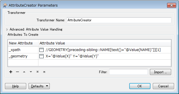
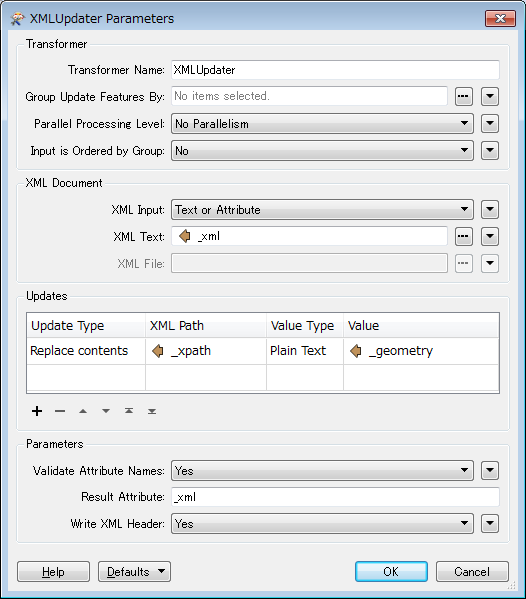
you can update the value of GEOMETRY element specified by the NAME with this workflow.
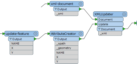
0684Q00000ArLW1QAN.png

0684Q00000ArLW6QAN.png

0684Q00000ArLRmQAN.png

See here to learn more about XPath: XPath Tutorial


Hi Takashi thank you for the detailed process. Yes my XML looks in a similar, the change in this is:

<?xml version="1.0"?>
<DATASET>
<FEATURE>
<NAME>AAA</NAME>
<GEOMETRY>X="123.456" Y="789.123"</GEOMETRY>
</FEATURE>
<FEATURE>
<NAME>XXX</NAME>    
<GEOMETRY>X="456.789" Y="123.456"</GEOMETRY>
</FEATURE>
<FEATURE>    
<NAME>ZZZ</NAME>    
<GEOMETRY>X="789.123" Y="456.789"</GEOMETRY>
</FEATURE>
</DATASET>

I will try the process explained above and will come back to you.

Thank you.

For that schema, the XPath expression can be easier like this.


//FEATUREÂchild::NAMEatext()="@Value(NAME)"]]/GEOMETRY 

attributecreator.jpgxmlupdater.jpg


I have tried the same. But throwing an error "

XMLUpdater(XQueryFactory2): invalid content passed to fn:parse-xml(): loader parsing error: Document is empty".

Can you check that the flow and the queries are correct or not. Please see the attached.flow.jpg

This is the actual xml format:

<?xml version="1.0"?>


<INVENTORY>


<STRUCTURE>


<GEOMETRY>X="123456.789" Y="987654.321"</GEOMETRY>


<STRUCTURE_NAME>ABC:DEF::1234</STRUCTURE_NAME>


</STRUCTURE>


</INVENTORY>
Firstly make sure that the feature that is input to the Document port has a valid XML document as an attribute called "GEOMETORY".


As I have mentioned above, the XML document contains the GEOMETRY tag as an attribute. If any issue in the above given XML, can you suggest the way forward.


As I have mentioned above, the XML document contains the GEOMETRY tag as an attribute. If any issue in the above given XML, can you suggest the way forward.

The attribute set to the 'XML Text' parameter of the XMLUpdater must store a valid XML document as its value. Does the "GEOMETRY" attribute contain a complete XML document?


Yes checked and finally issue solved. Thank you for the great support. Now i am trying for linear features which will have multiple geometry tags inside geometries tag..like

<?xml version="1.0"?>


<INVENTORY>


<LINEAR>

<GEOMETRIES>


<GEOMETRY>X="123456.789" Y="987654.321"</GEOMETRY>

<GEOMETRY>X="1234.789" Y="987.321"</GEOMETRY>

</GEOMETRIES>


<STRUCTURE_NAME>ABC:DEF::1234</STRUCTURE_NAME>


</LINEAR>


</INVENTORY>
A possible way is:


  1. Create new <GEOMETRIES> element that contains multiple child <GEOMETRY> elements.
  2. Replace the original <GEOMETRIES> element in the source XML document with the new <GEOMETRIES> element, using the XMLUpdater transformer (Update Type: Replace, Value Type: XML/XQuery).
I think the XMLTemplater can be used to create the new <GEOMETRIES> element, but the required procedure depends on how the updated geometry information is given.


Hi Takashi, Yes as guided and with your continuous great support, i have used the XMLTemplater and XMLUpdater to update the geometries in linear features. Everything is done. After all the ready XMLs, i have loaded the data and it looks good. But observed some deviation in the coordinates with respect to the data which is transformed through the ESRI in built Transformation functionality. Please find the deviation in the graphical representation also in the attached testing-fme.jpg. Polygons are the top view of the Buildings, "Circles" on it are the Features transformed using ESRI in built transformation functionality and "Rectangle with a Brown dot in it" are the features(almost of these feaatures are at the edge of the buildings) transformed through FME.

Please can you comment on the reason for deviation and suggest me further.

Looks like the deviation is caused by wrong coordinate system setting. Check if the coordinate system is set correctly for each dataset.


I am transforming the coordinates from Naparima 1955/UTM zone 20N to UTM-WGS 1984 zone 20N. Please find the attached snapshot reprojector.jpg for the source and target coordinate systems set in Reprojector and suggest further.


I am transforming the coordinates from Naparima 1955/UTM zone 20N to UTM-WGS 1984 zone 20N. Please find the attached snapshot reprojector.jpg for the source and target coordinate systems set in Reprojector and suggest further.

Transforming coordinate system may not be a matter here. I suspect that the coordinate system itself that is set to one of those datasets could be wrong.


If you open the two datasets (the "Circles" and the "Rectangle with a Brown dot in it") with FME Data Inspector, would the deviation still appear?


Hi Takashi, Yes as guided and with your continuous great support, i have used the XMLTemplater and XMLUpdater to update the geometries in linear features. Everything is done. After all the ready XMLs, i have loaded the data and it looks good. But observed some deviation in the coordinates with respect to the data which is transformed through the ESRI in built Transformation functionality. Please find the deviation in the graphical representation also in the attached testing-fme.jpg. Polygons are the top view of the Buildings, "Circles" on it are the Features transformed using ESRI in built transformation functionality and "Rectangle with a Brown dot in it" are the features(almost of these feaatures are at the edge of the buildings) transformed through FME.

Please can you comment on the reason for deviation and suggest me further.

Maybe also verify that the number of decimals in the output XML is sufficient.


Please find the attached snapshot fme-data-inspector.jpg from the FME Data inspector. Please observe the deviation, Black color features transformed through ESRI in built functionality. Blue color features transformed through FME. Please suggest. If required, for further details, we can discuss one to one..


Please need your comments on the above issue. So is it that deviation will be available if we use Reprojector? Is there any way to transform to the coordinates to match the ESRI transformed coordinates?


Please need your comments on the above issue. So is it that deviation will be available if we use Reprojector? Is there any way to transform to the coordinates to match the ESRI transformed coordinates?

There is indeed, look for the EsriReprojector.

Thank you for the information. I am unable to find the EsriReprojector. Do i need to install any plugins for that ?


Thank you for the information. I am unable to find the EsriReprojector. Do i need to install any plugins for that ?

You need a licensed installation of ArcGIS on your machine where FME is running. I'm also not so sure if the EsriReprojector works with 64-bit FME just yet.


You need a licensed installation of ArcGIS on your machine where FME is running. I'm also not so sure if the EsriReprojector works with 64-bit FME just yet.


Seems like it should work with the 64-bit FME as well, although there are some dependencies. Look here: https://knowledge.safe.com/questions/29824/how-can-i-avtivate-the-esrireprojector.html


I am getting an error while using ESRIReprojector. Please suggest . The error is "Esri Reprojector: Specified geotransformation `' (forward) may be inappropriate for reprojection from `Naparima55.UTM-20N' (GCS: `GCS_Naparima_1955') to `UTM84-20N' (GCS: `GCS_WGS_1984') using the ESRI reprojection engine"


Reply