Solved

IF loop in FME with creator (i++)

  • 13 March 2024
  • 6 replies
  • 111 views

Badge +1

​Hello guys, Damjan here,

i have problems with my FME process so i need your help. 


Task:

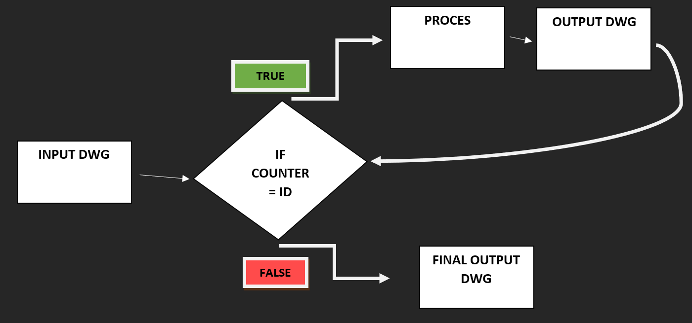
I have 1 dwg file with 6 polylines (3 pairs), each pair must go to PROCES (process makes a polyline between 1 pair, that's fine all works), then process must save this polyline in dwg and go to start for next pair.

Shema:


FME:

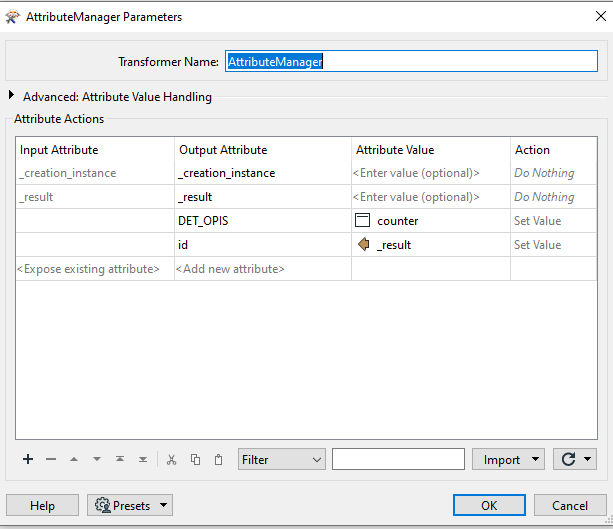
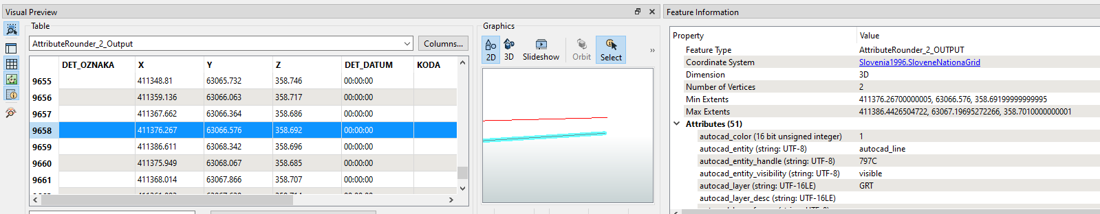
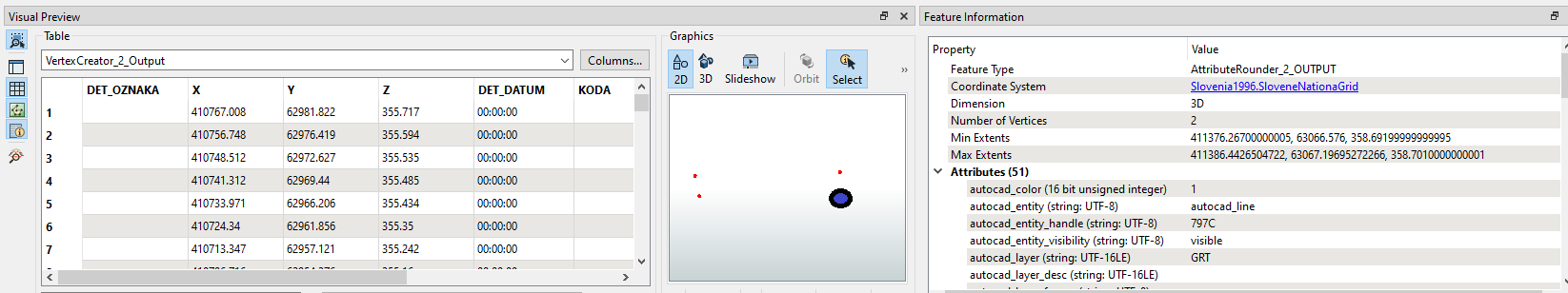
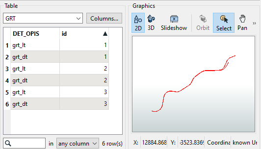
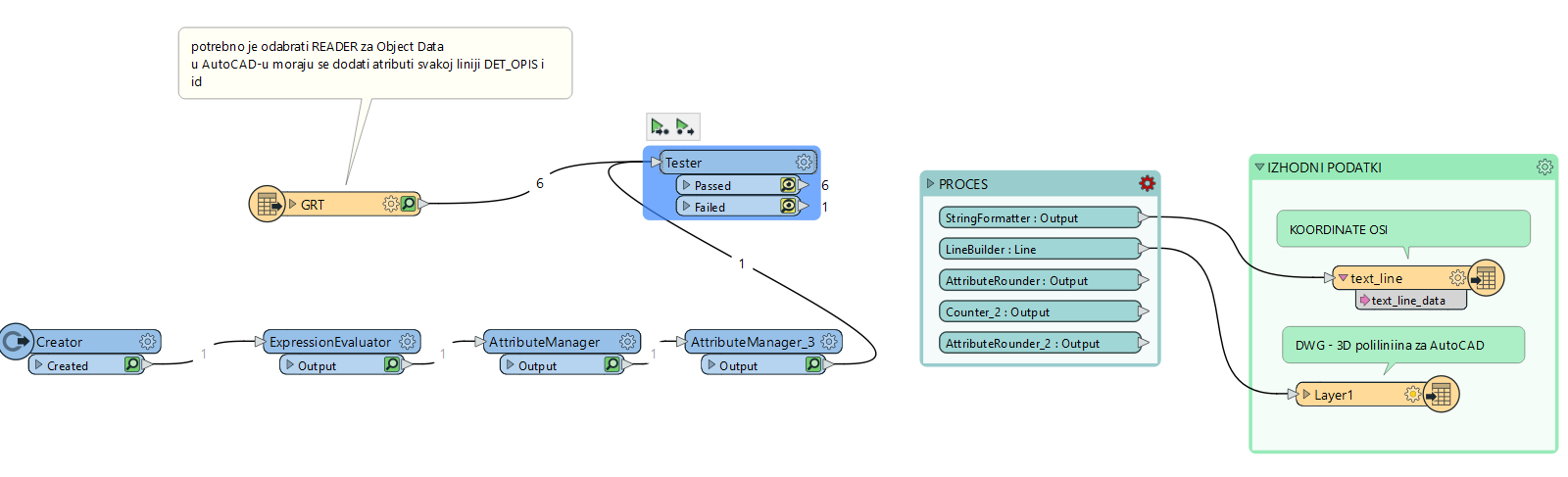
DWG GRT: Each polyline has an attribute id which represent pairs (for example: 2 polylines (grt_dt & grt_lt) have the same id which means they are 1 pair), the second attribute is Description (DET_OPIS): grt_dt = right polyline, grt_lt = left polyline.


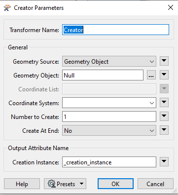
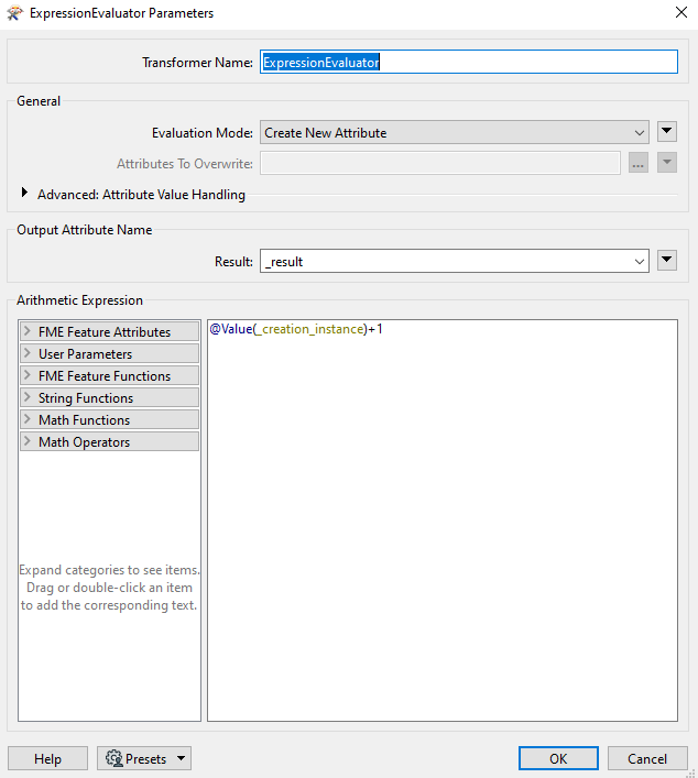
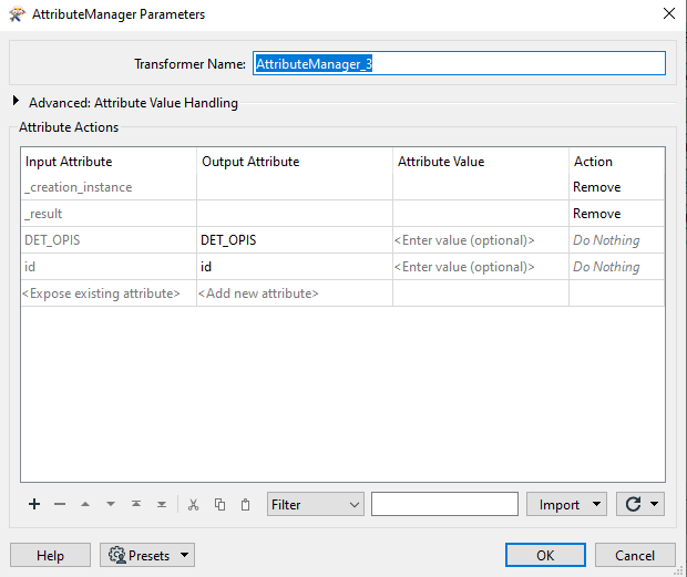
I add Creator to make counter, with the Attribute manager making the same attribute like in dwg (GRT), and then connect to tester. My idea is that the tester test if value of counter equals to id. If its true, then go to process, when process finish, save to dwg format and then go to start for next pair. 


Problem:

I have problem in tester cause i dont know how to setup tester to make him work. 

If anyone know how to fix that or know some other solution dor my problem, please help me.


Thank you

Cheers.


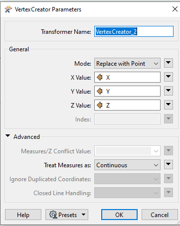
P.S.: I put pics of setup of each transformer, scroll down.

icon

Best answer by nielsgerrits 13 March 2024, 15:21

View original

6 replies

Userlevel 3
Badge +18

I’m not sure what you want to achieve, but I think you misunderstood the functionality of the Tester, a Tester evaluates each feature against one or more user-defined tests, see docs:

https://docs.safe.com/fme/html/FME-Form-Documentation/FME-Transformers/Transformers/tester.htm


You don’t need to loop either if I understand your case well, you’ll need some Python or custom transformers to loop anyways.


The point here, I guess, is to set the correct ‘Group By’ settings in your ‘PROCES’-bookmark. Set Group By to id and the processing is done for each group of features (id by id) separately. Maybe this is a good starting point: https://docs.safe.com/fme/html/FME-Form-Documentation/FME-Transformers/Group_Based_Transformers.htm 

Userlevel 5
Badge +26

I’m trying to get my head around this.


I don’t think you need the Creator path and all that, I think (based on what you do in processing) you should look into the Fanout option in your DWG writer (write different DWG’s based on attribute values) and perhaps a group by option in the processing.

Userlevel 6
Badge +34

Despite the very complete question, I have a hard time understanding what you try to achieve.

If I understand correctly, you have sets of lines with corresponding id’s. You want to process these lines and write the result to a cad file per set.

There are different ways to solve this:

  • Group By
    • A lot of transformers have a Group By function, which you can use to subbproces features which have a common id.
  • Custom transformer
    • Create a custom transformer and configure it to do the group by over the entire custom transformer.
  • Workspacerunner
    • Create a child worspace where the work is done and a parent workspace which initiates the child to do the work.

When writing, you can just use a FeatureWriter and use the common id as input for the filename, which will result in a file per common id.

I attached a sample workspace demonstrating the Group By and the Custom transformer. If I misunderstood, try and explain what you want, with a printscreen or .FFS file of the input and expected output.


Badge +1

@nielsgerrits @becchr @redgeographics thanks guys for reply. 

I found solution for my problem, I edit my NeighbourPairFinder transformer and add Group by Process into transformer.

Unfortunately I have a new problem… I want to create vertex from line and it's work for 95% points, but transformer want to create some points. I don't get it why, I try to move vertex in dwg, change Z coordinate but every time it's the same, won't create point

Where is blue/dark dot must be the point, but isn't:

P.S. Thank you guys so much for useful advices, you save my time :D

Userlevel 6
Badge +34

@nielsgerrits @becchr @redgeographics thanks guys for reply. 

I found solution for my problem, I edit my NeighbourPairFinder transformer and add Group by Process into transformer.

Unfortunately I have a new problem… I want to create vertex from line and it's work for 95% points, but transformer want to create some points. I don't get it why, I try to move vertex in dwg, change Z coordinate but every time it's the same, won't create point

Where is blue/dark dot must be the point, but isn't:


P.S. Thank you guys so much for useful advices, you save my time :D

Always hard to say without data, when I have these issues, I isolate the subset and let only those features throught which cause issues to research.

Badge +1

@nielsgerrits

The task I am doing is complex, but I will try to explain it as briefly but clearly as possible.
 
1. I have polylines with id and DET_OPIS attributes - dwg
2. From polylines I need to get points (coordinates X Y Z)
3. I need to find the middle point between two opposite points - I use the NeighborPairFinder transformer
4. with the middle points I have to draw one polyline which will be the middle line

I also added a zip file with data, I hope it will be clearer now

thank you

Reply