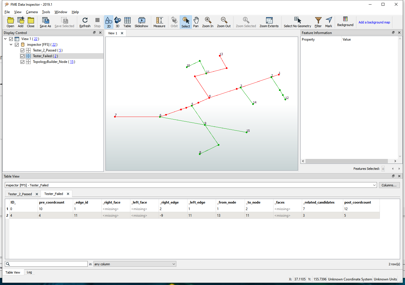
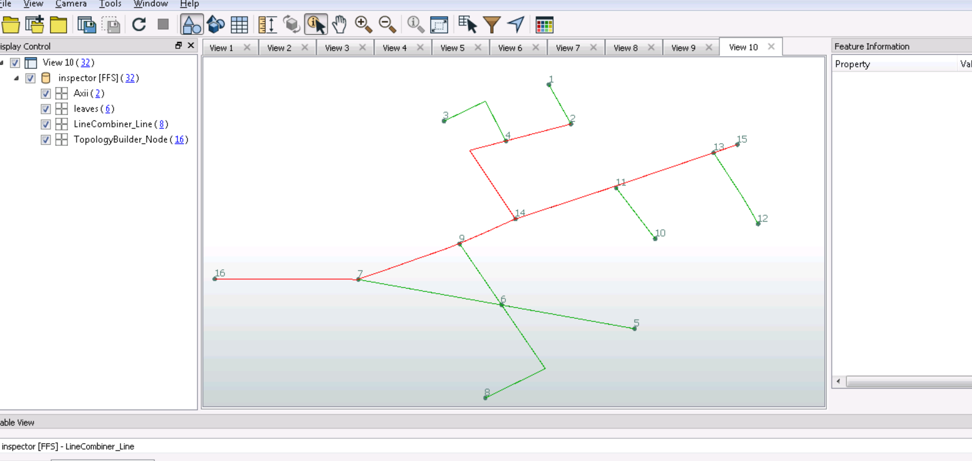
i have tried to use intersector and topolgoy builder to identify nodes that intersected

but i am not sure how could i recognize only the node of starting branch because some node has 3 overlaps and one at the end has only two overlaps .

it means only two lines intersected with eachother ,

So it will be hard to recognize by overlaps because At some branches to red point ,the lines intersected to eachother ,so it will have also 2 overlaps.

each line has his own id but from the vertex in front of Grey Arrow has 2 or 3 Lines till reach End point .

the main line has many connected lines

i have tried with neighbor finder but my main problem how could i recognize the the vertex in front of Grey Arrows .

Is there way to use neighbor finder and add Tester to stop at Vertex in front of Gray Arrow

FME 2018


Thanks for help in Advance


I had to build a similar Network Data Model from FME. Broadly it was:

  1. Determine Node vs Edge Topology using TopologyBuilder (From the Nodes Output Port)
  2. For the Branch Connection Nodes (Grey Points) split the Network Edges using a Snipper to disconnect the Branch lines from the Mains to make them into their own mini subnetworks by snipping off 1 mm from the ends of the Edges that entered the Branch Connection Node.
  3. Use a NetworkToplogyCalculator to assign a common NetworkID to the now split up/broken parts of the Network. I didn't care about the result for the Mains, but what this did was put a NetworkID grouping around the Branch Edges, as similarly the Branches could consist of 1 or more line edge segments.
  4. The Branch Subnetworks were the ones that had an Edge ID that matched an Edge ID on the Branch Service Point (End Point). The output of the TopologyBuilder Nodes Port had this information once the Edge List for each Node was exploded with a ListExploder which gave Node ID vs Edge ID.
  5. If there was an Edge that joined to a Branch Service (End) Point, then the workflow determined what the NetworkID was for that Edge (as this had been calculated with NetworkTopologyCalculator), and then all Branch edges within that Branch subnetwork with the same NetworkTopologyCalculator NetworkID was therefore part of that Branch, and any Edges NOT part of these Branch Subnetworks were part of the Mains Network.

Thanks a lot for replying ,it looks great idea ,i will do that and i will tell u the result .


@gogopotter90 an alternative approach is to identify the lateral lines (or service line) and flag them - the remaining lines will be your network.

Use SpatialRelator, or PointOnLineOverlayer to match your end points to lines. Any line that touches an end point looks like it will be a lateral line. Any line that does not touch an end point looks like it will be a main.


I had to build a similar Network Data Model from FME. Broadly it was:

  1. Determine Node vs Edge Topology using TopologyBuilder (From the Nodes Output Port)
  2. For the Branch Connection Nodes (Grey Points) split the Network Edges using a Snipper to disconnect the Branch lines from the Mains to make them into their own mini subnetworks by snipping off 1 mm from the ends of the Edges that entered the Branch Connection Node.
  3. Use a NetworkToplogyCalculator to assign a common NetworkID to the now split up/broken parts of the Network. I didn't care about the result for the Mains, but what this did was put a NetworkID grouping around the Branch Edges, as similarly the Branches could consist of 1 or more line edge segments.
  4. The Branch Subnetworks were the ones that had an Edge ID that matched an Edge ID on the Branch Service Point (End Point). The output of the TopologyBuilder Nodes Port had this information once the Edge List for each Node was exploded with a ListExploder which gave Node ID vs Edge ID.
  5. If there was an Edge that joined to a Branch Service (End) Point, then the workflow determined what the NetworkID was for that Edge (as this had been calculated with NetworkTopologyCalculator), and then all Branch edges within that Branch subnetwork with the same NetworkTopologyCalculator NetworkID was therefore part of that Branch, and any Edges NOT part of these Branch Subnetworks were part of the Mains Network.

Could I ask about snipper,because I did not use it before and I got rejected .i am not sure if I do sth.wrong.

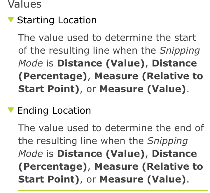
I have chosen snipping mode Distance

Starting location 0

Ending location -0.01

Could I ask ,does it correct way to snip 0.01 from the end of edges ,or what should I do


@gogopotter90 an alternative approach is to identify the lateral lines (or service line) and flag them - the remaining lines will be your network.

Use SpatialRelator, or PointOnLineOverlayer to match your end points to lines. Any line that touches an end point looks like it will be a lateral line. Any line that does not touch an end point looks like it will be a main.

It is simple idea ,but my problem the line from the main line till reach the end point ,it is not only one single line ,it consists of many lines,do u have any suggestion how could I recognize the line touches with end point till reach the intersected point with main line .intersected nodes with the main line unknown for me .Thanks for help


It is simple idea ,but my problem the line from the main line till reach the end point ,it is not only one single line ,it consists of many lines,do u have any suggestion how could I recognize the line touches with end point till reach the intersected point with main line .intersected nodes with the main line unknown for me .Thanks for help

@gogopotter90 if there are any number of line segments between the end point and the 'main' then you're hooped. If there is only one or two segments, then you could possibly use SpatialRelator to make a second guess at whether its a lateral line of main.


@gogopotter90 if there are any number of line segments between the end point and the 'main' then you're hooped. If there is only one or two segments, then you could possibly use SpatialRelator to make a second guess at whether its a lateral line of main.

Thanks for ur suggestion to use SpatialRelator but unfortunately,I do not have limit number of Segment sometimes 3 sometimes 2 or 4, it depends . But I will try to use SpatialRelator and work around ur suggestion to find suitable solution for my issue.Thanks a lot


Could I ask about snipper,because I did not use it before and I got rejected .i am not sure if I do sth.wrong.

I have chosen snipping mode Distance

Starting location 0

Ending location -0.01

Could I ask ,does it correct way to snip 0.01 from the end of edges ,or what should I do

To trim off 1 centimetre from the beginning of the Line, it is measured relative to the Start Point:

  • Starting Location = 0
  • Ending Location = 0.01

To trim off 1 centimetre from the end of the Line, it is

  • Starting Location = @Length()-0.01
  • Ending Location = @Length()

If for whatever reason you have line segments less than 1 centimetre in length, that would cause an error with the above values, alternatively you can also use Distance (Percentage) mode and say use values of 0 (%) and 5 (%) for trimming off the start of the line, and 95 (%) and 100 (%) for trimming off the ends of the line, depending on whether it is the Start Point or the End Point of the Branch line that connects to the Mains-Branch connection point (Grey Nodes).

Another handy thing the TopologyBuilder Nodes Port does is tell you in which direction the Branch line going into the node is going: Whether it is a Start Point intersection or an End Point intersection.

If you have reversed lines, then you can use either Conditional Values to handle both situations in the one Snipper, or just send the 2 line orientation scenarios to 2 different Snippers.

Thanks alot for replying


@gogopotter90


Hi assuming this is what youwant

gogo36845 


the this workbench does it.

F_36845_pre.fmwt


The most of the work is into catching the crossing lines. (i'm assuming there is no bridge there. For that a litle adaptiation is required)


Basicaly node and vertex counting and comparing.


greetz and stay healthy!

@gogopotter90


Node 13, not as you wish. Down to how i drew that line. Should tackle that sometime.

@gogopotter90


Hi assuming this is what youwant

gogo36845 


the this workbench does it.

F_36845_pre.fmwt


The most of the work is into catching the crossing lines. (i'm assuming there is no bridge there. For that a litle adaptiation is required)


Basicaly node and vertex counting and comparing.


greetz and stay healthy!

thanks for ur workspace but i have FME version 2018 ,could you please provide me workspace suitable for 2018 .

about node 13 , i am still thinking about which point connects to two end point at the same time then i try to find the next intersecting in this line,but i am not sure how could i decide ,for which line that has end point to follow ,and also if i have two more segment in the main line that connects to node 13 so it means i did not need the first vertex ,the second vertex at this main .Thanks alot


@gogopotter90


Hi.

I converted it to fme2018.

Had to fiddlel a bit as topology builder has no list building and has different behaviour.

Here is workspace F_36845_pre.fmwt

IT works nice with correct netwerk (is same for 2019 version)

36845-quest


@gogopotter90


Hi.

I converted it to fme2018.

Had to fiddlel a bit as topology builder has no list building and has different behaviour.

Here is workspace F_36845_pre.fmwt

IT works nice with correct netwerk (is same for 2019 version)

36845-quest

thanks for ur workspace ,it seems that u did great job .


@gogopotter90


Hi assuming this is what youwant

gogo36845 


the this workbench does it.

F_36845_pre.fmwt


The most of the work is into catching the crossing lines. (i'm assuming there is no bridge there. For that a litle adaptiation is required)


Basicaly node and vertex counting and comparing.


greetz and stay healthy!

I can't seem to find the sample workbench "F_36845_pre.fmwt" that you attached in your response. Would it be possible for you to share for me to have a look?


I can't seem to find the sample workbench "F_36845_pre.fmwt" that you attached in your response. Would it be possible for you to share for me to have a look?

Hi.


Yes of course.


Greets.


@gogopotter90


Hi assuming this is what youwant

gogo36845 


the this workbench does it.

F_36845_pre.fmwt


The most of the work is into catching the crossing lines. (i'm assuming there is no bridge there. For that a litle adaptiation is required)


Basicaly node and vertex counting and comparing.


greetz and stay healthy!

Hi @gio,


Appreciate your help. Thank you very much.


I am new to FME and brushing my skills. So apologies if I am asking silly questions. I have a TAB (Mapinfo) file of a network. As an example, consider a telecom network. What I am trying to achieve is just the end nodes of the network. I do not want to the nodes at junctions where network lines meet. Your example also extracts intermediate nodes as well.


Would it be possible for you to help in this regard?


Thanks.

Hi @mukeshrvyas​ 


Yes, this workbench was specifically made for the node etc. detection( see original ppost)


Detecting just endnodes is less complex.

Especially if you use fme 2019 or higher.

Because the Topologybuilder in those versions have list-generation.


Maybe your network already has the info on it (have not seen sample data).

So all you need to do is test the list on the nodes. Endnodes have only one line_id. (or one lement)


Greets,

Gio


Reply