HI All,
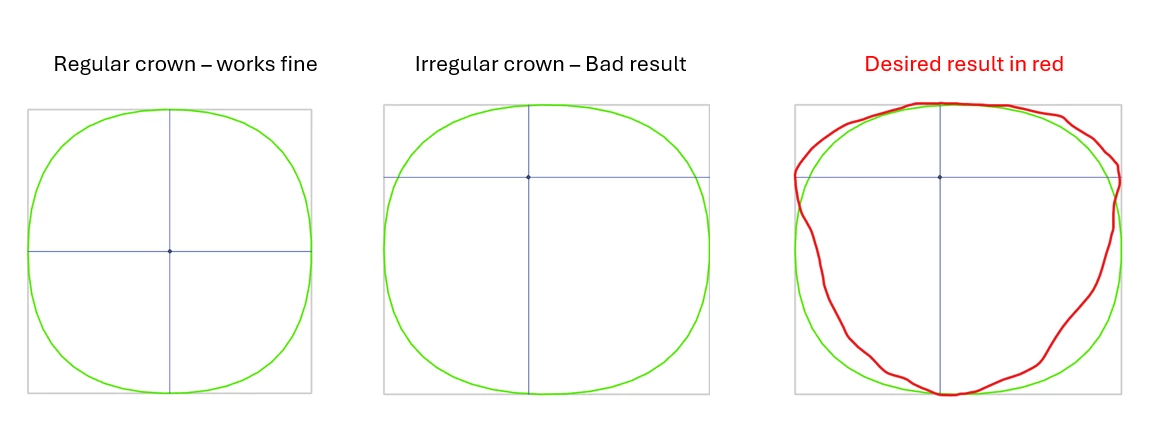
I have a bit of geometry challenge to create a rectangle (or square) polygon based on a cross geometry, some example below:
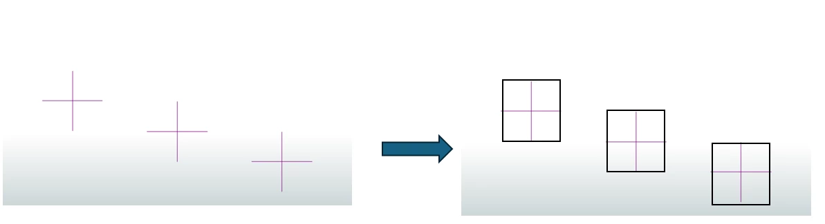
Any ideas how to achieve this?
Thanks :)


 +22
+22HI All,
I have a bit of geometry challenge to create a rectangle (or square) polygon based on a cross geometry, some example below:
Any ideas how to achieve this?
Thanks :)
Best answer by DanAtSafe
Hi
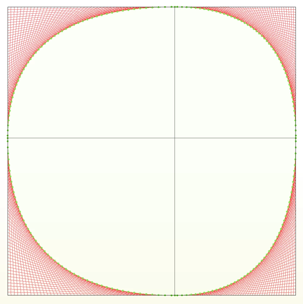
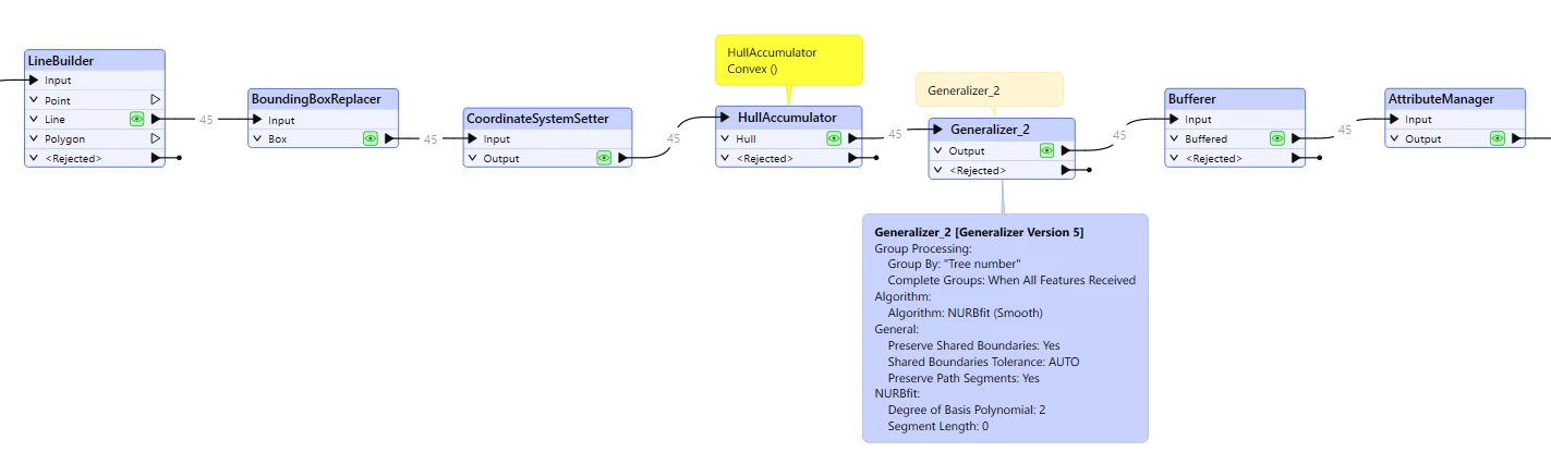
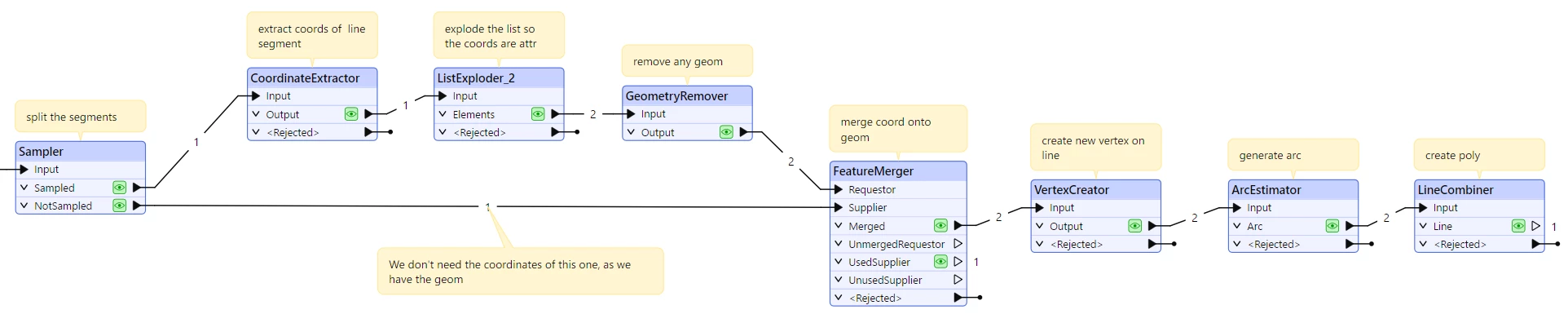
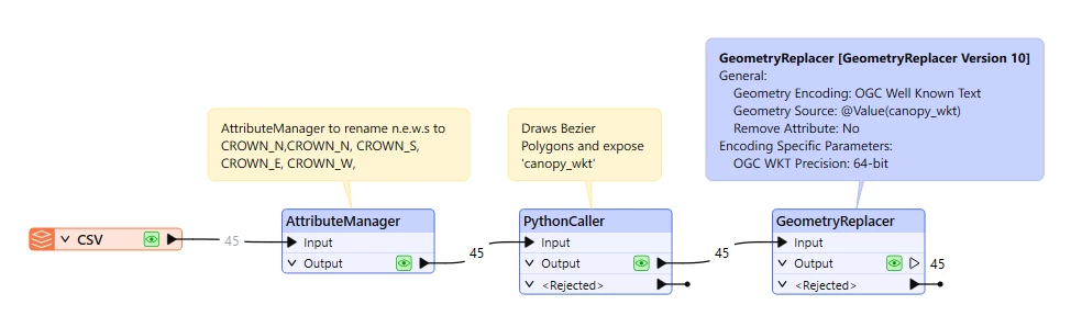
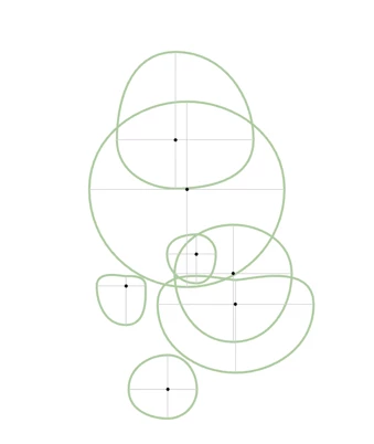
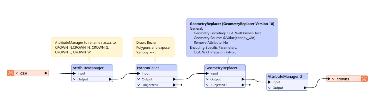
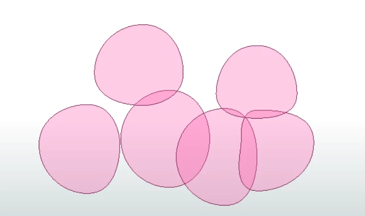
This workspace approximates that without creating actual curves or arcs.
No account yet? Create an account
Enter your E-mail address. We'll send you an e-mail with instructions to reset your password.