Howdy,

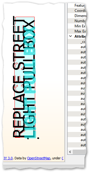
I am reading with an AutoCAD .dwg and I need FME to generate a bounding polygon around annotation text as the text it appears in Inspector.

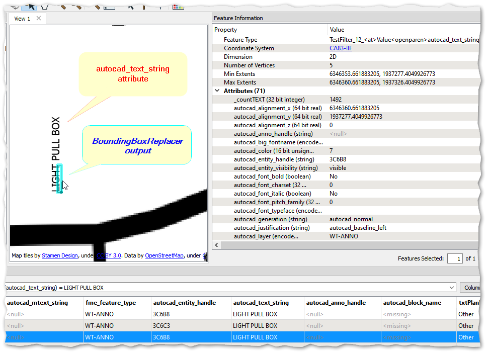
I used the BoundingBoxReplacer to generate a polygon for the extents of the text, however as you can see in the screen capture below the bounding box output is significantly smaller than the text as the text appears in the Inspector.


Can someone please help me understand how FME is deciding the size/extents of the bounding box? What do I need to do get a bounding box output that matches up with the actual text extents??


Please see the attached data if needed:
Thank you!


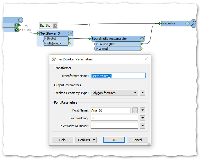
Have you tried using a TextStroker transformer, before generating the bounding box, using the BoundingBoxAccumulator (group by the id of the text)?

Hope this helps.


Have you tried using a TextStroker transformer, before generating the bounding box, using the BoundingBoxAccumulator (group by the id of the text)?

Hope this helps.

TextStroker it is! I've never had opportunity to use that one before, thank you for pointing me in the right direction.


It took a couple of tries to get the font/size/padding/width parameter's sorted but I got it pretty close for the most part.

For the next person hunting for this solution, here's the parameters I ended up with:


Reply