Hi everyone,

I have a workspace to create polygons from point with aixm 4.5 data (previous question here, thank you @takashi)

Somes of the polygons contains arcs, and theirs direction clockwise (CWA) or anti-clock wise (CCA) matters, I don't know how to handle this in python, or with other transformer.

Any ideas ? Thanks

Wouldn't it simply be a case of exchanging the coordinates of start of arc with the coordinates of end of arc to inverse the arc direction? Or maybe I'm misunderstanding the question.

Although the simplest may be to use an Orientor transformer after the PythonCaller to force each polygon in a certain orientation.

Hello, I tried to use the orientor but it doesn't seem effective


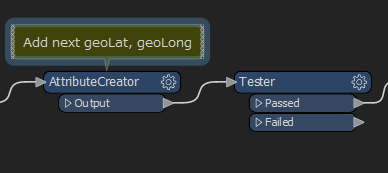
This part of the workspace needs altering to make sure the last arc is included

You need to create a startLong and startLat for each feature, then for the last point in a feature set the nextgeoLat and nextgeoLong to be the start point of the feature. The tester can then be removed.

create-arc-with-python-example.fmwt

I think there are still issues with clockwise v counter clockwise but that is a separate issue.


For the clockwise/counterclockwise issue you could replace the last line of the python code with this, I'm sure there's probably a way to do the maths before you create the arc but it's too early on a Monday morning. 

    arcdirection = feature.getAttribute('codeType')
    geom = fmeobjects.FMEArc(threePoints)
    
    if arcdirection =='CWA' and geom.isCW():
        feature.setGeometry(geom)
    elif arcdirection == 'CCA' and geom.isCW()==False:
        feature.setGeometry(geom)
    else:
        x1, y1 = xc - vx1 / len * radius, yc - vy1 / len * radius
        threePoints = (
        fmeobjects.FMEPoint(x0, y0),
        fmeobjects.FMEPoint(x1, y1),
        fmeobjects.FMEPoint(x2, y2)
    )
    
        geom = fmeobjects.FMEArc(threePoints)
        feature.setGeometry(geom)
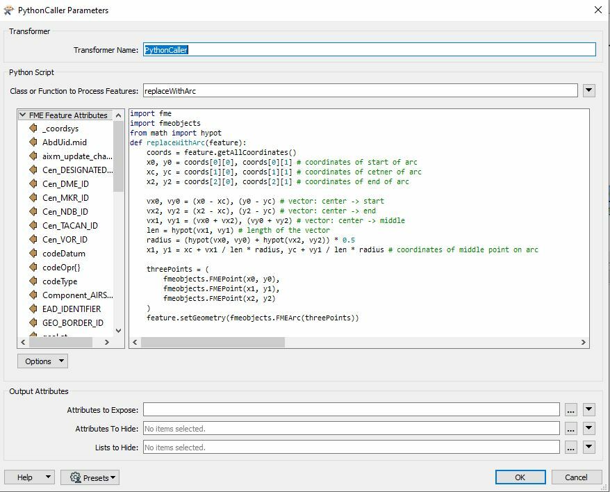
Hi @sandry, I'm not sure why you need to modify CW/CCW of the arc.

Imagine where you draw an arc connecting two points (start and end) using a compass. You can draw two arcs with an identical radius, and CW/CCW is determined according to the location of the center. In other words, CW/CCW of an arc is naturally determined, if its start point, center and end point are given.

The script I provided in the previous question creates an arc based on coordinates of start point, center and end point which all are given by the input feature. I therefore think the resulting arc has correct CW/CCW, unless the source data was wrong.

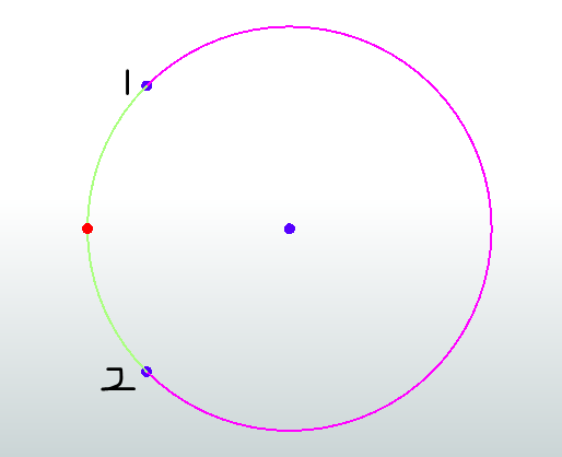
In the python above, the centre point of the arc(x1,y1) - red is calculated from the centre of the circle that would create the arc (xc,yc) - blue. The centre of the circle is given in the input data


The input data contains a codeType attribute that describes whether the arc is clockwise (pink) or counterclockwise (green)


Hi @sandry, I'm not sure why you need to modify CW/CCW of the arc.

Imagine where you draw an arc connecting two points (start and end) using a compass. You can draw two arcs with an identical radius, and CW/CCW is determined according to the location of the center. In other words, CW/CCW of an arc is naturally determined, if its start point, center and end point are given.

The script I provided in the previous question creates an arc based on coordinates of start point, center and end point which all are given by the input feature. I therefore think the resulting arc has correct CW/CCW, unless the source data was wrong.

@ebygomm, you are right. Two arcs can be drawn for the same start - center -end. We have to check the "codeType" attribute to determine CW or CCW.


thank you @ebygomm (and @takashi again), the workspace and code you provide solved the bigest problem !


May I abuse your kindness and your time once more ? It seems like arcs with larger radius are acting in an unexpected way, while smaller ones are completly fine.

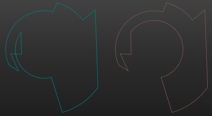
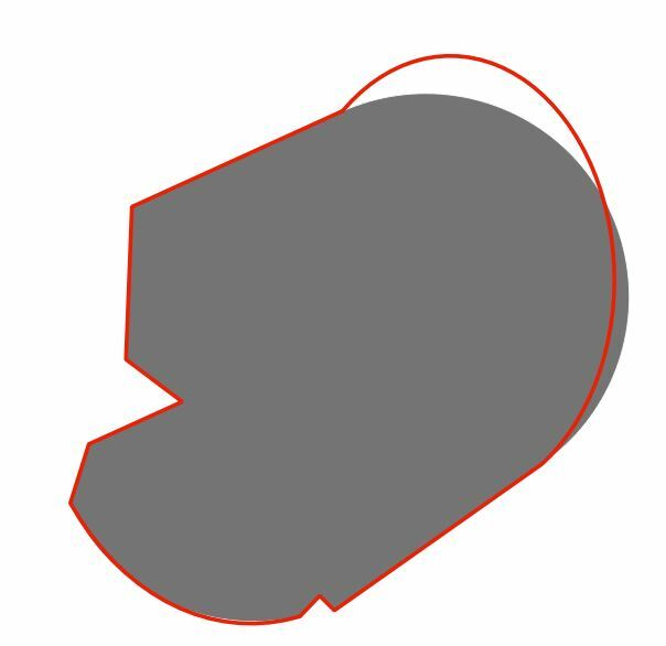
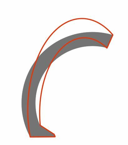
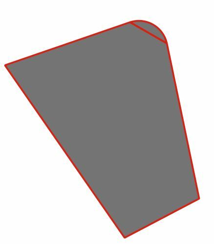
here you can see in grey the expected geometry and red the result. Both arcs are not correct, it's less oubvious for the bottom one. In the data both are supposed to be CWA 24 nm radius.

This is not a projection problem, I have checked .

Do you have an identifier for the above feature, or a location?


Do you have an identifier for the above feature, or a location?

The above feature isn't in the data subset I shared with you, but the same problem can be found with the ead_identifier 'CTA-P_EIDW06'

this time it's CWA and 25 nm


The above feature isn't in the data subset I shared with you, but the same problem can be found with the ead_identifier 'CTA-P_EIDW06'

this time it's CWA and 25 nm


I don't get the same result for that example

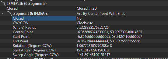
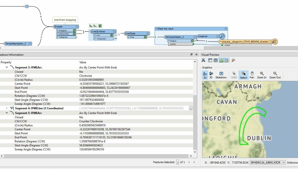
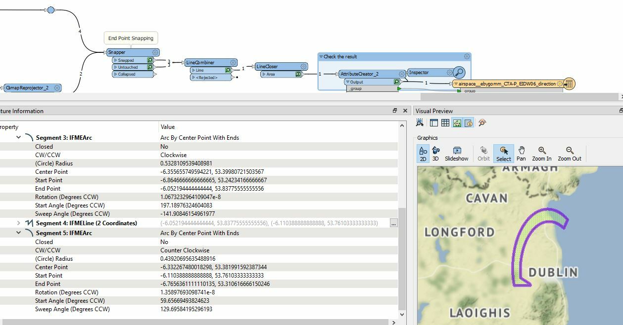
If you select the geometry and look in the feature information window, are the IFMEArc's still described as Arc By Center Point with Ends?


I don't get the same result for that example

If you select the geometry and look in the feature information window, are the IFMEArc's still described as Arc By Center Point with Ends?

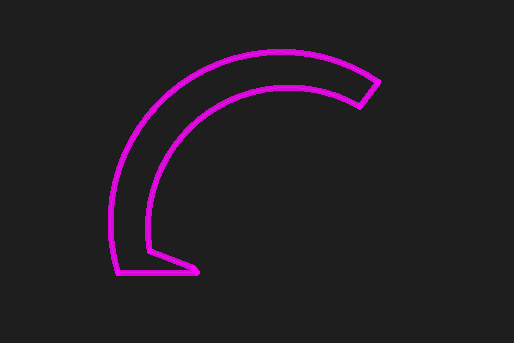
yes, here are the results after the line combiner

and after the line closer


thank you @ebygomm (and @takashi again), the workspace and code you provide solved the bigest problem !


May I abuse your kindness and your time once more ? It seems like arcs with larger radius are acting in an unexpected way, while smaller ones are completly fine.

here you can see in grey the expected geometry and red the result. Both arcs are not correct, it's less oubvious for the bottom one. In the data both are supposed to be CWA 24 nm radius.

This is not a projection problem, I have checked .

In my observation, the Snapper in the workspace slightly moves end nodes of some arcs. It seems that FME transforms those snapped arcs "arc by 3 points" to "arc by center point and ends" automatically and this causes the unexpected elliptic arcs. Which arcs would be transformed seems to depend on projected coordinate system (@ebygomm has used EPSG:2157, I've used _AZMED_).

A quick workaround is to insert an ArcStroker between the PythonCaller and the next CsmapReprojector to keep approximate shapes regardless of coordinate system, if you allow to change geometry type from IFMEArc to IFMELine.


yes, here are the results after the line combiner

and after the line closer

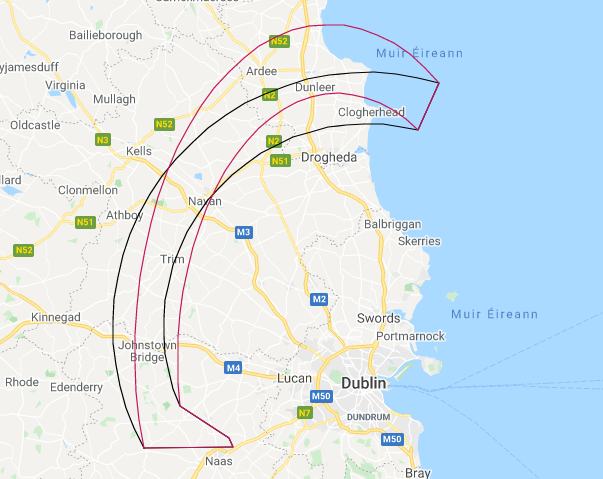
It is something to do with the reprojection and the way the arcs have been created with Arc By 3 Points. Displayed over web mapping Arc by 3 points is shown in red

If the arcs are created as Arc By Center Point With Ends the result looks more appropriate (shown in black)


In my observation, the Snapper in the workspace slightly moves end nodes of some arcs. It seems that FME transforms those snapped arcs "arc by 3 points" to "arc by center point and ends" automatically and this causes the unexpected elliptic arcs. Which arcs would be transformed  seems to depend on projected coordinate system (@ebygomm  has used EPSG:2157, I've used _AZMED_).

A quick workaround is to insert an ArcStroker between the PythonCaller and the next CsmapReprojector to keep approximate shapes regardless of coordinate system, if you allow to change geometry type from IFMEArc to IFMELine.

I revised my script, for what it's worth.

import fme
import fmeobjects
from math import hypot
def replaceWithArc(feature):
    coords = feature.getAllCoordinates()
    x0, y0 = coordso0]b0], coordse0]a1] # coordinates of start of arc
    xc, yc = coordsl1]o0], coords<1] 1] # coordinates of center of arc
    x2, y2 = coordsd2]a0], coordst2]t1] # coordinates of end of arc
    radius = (hypot((x0 - xc), (y0 - yc)) + hypot((x2 - xc), (y2 - yc))) * 0.5
    
    dist = hypot((x2- x0), (y2- y0)) # distance between start and end
    ux, uy = (x2 - x0) / dist, (y2 - y0) / dist # unit vector: start -> end
    
    # Calculate coordinates of middle point on arc
    if feature.getAttribute('codeType') == 'CWA':
        x1, y1 = xc - uy * radius, yc + ux * radius
    else:
        x1, y1 = xc + uy * radius, yc - ux * radius
        
    threePoints = (
        fmeobjects.FMEPoint(x0, y0),
        fmeobjects.FMEPoint(x1, y1),
        fmeobjects.FMEPoint(x2, y2)
    )
    feature.setGeometry(fmeobjects.FMEArc(threePoints))

I revised my script, for what it's worth.

import fme
import fmeobjects
from math import hypot
def replaceWithArc(feature):
    coords = feature.getAllCoordinates()
    x0, y0 = coordsÂ0] 0], coords00]=1] # coordinates of start of arc
    xc, yc = coords 1]Â0], coordsÂ1] 1] # coordinates of center of arc
    x2, y2 = coordss2]o0], coords 2]Â1] # coordinates of end of arc
    radius = (hypot((x0 - xc), (y0 - yc)) + hypot((x2 - xc), (y2 - yc))) * 0.5
    
    dist = hypot((x2- x0), (y2- y0)) # distance between start and end
    ux, uy = (x2 - x0) / dist, (y2 - y0) / dist # unit vector: start -> end
    
    # Calculate coordinates of middle point on arc
    if feature.getAttribute('codeType') == 'CWA':
        x1, y1 = xc - uy * radius, yc + ux * radius
    else:
        x1, y1 = xc + uy * radius, yc - ux * radius
        
    threePoints = (
        fmeobjects.FMEPoint(x0, y0),
        fmeobjects.FMEPoint(x1, y1),
        fmeobjects.FMEPoint(x2, y2)
    )
    feature.setGeometry(fmeobjects.FMEArc(threePoints))

The ArcStroker did the trick !

One last thing, I just realise I have more output feature than unique identifier, meaning some polygons are divided in multiple ones.


In grey the expected feature (1 polygon)  and red the result divided in 2 polygons

here the ead_identifier is RAS_ENLE

0684Q00000ArNRNQA3.jpg


Reply