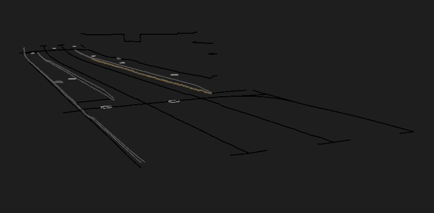
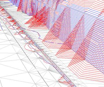
I am trying to create a TIN-model with FME using the TINGenerator. Picture below shows (red) whats generated with FME and another software (blue).
As can be seen the breaklines does not get handled well. Is there any way to tweak the data so it can handle breaklines better? I have tried using the following transformers:
- Densifier
- Generalizer
- PointCloudCombiner
However it does not seem to handle breaklines very well. Breaklines shown on GREEN line in the image below
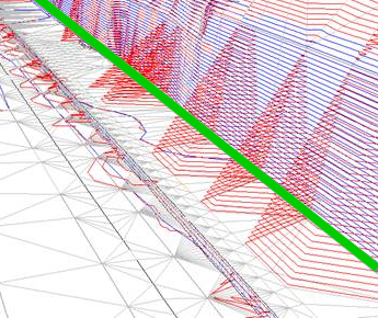


 Also, FME doesn't like using areas as brakelines so check if your "green" lines are open or closed.