Solved

Some issues with the coordinate system on 3d tiles.


Forum|alt.badge.img

Hi.

I tried a lot of formats to convert 3d tiles, but the result was not good.I mainly want to talk about some of the problems with the coordinate system during COLLADA's conversion of 3d tiles.There are two sources for my COLLADA files, the first one is exported from Blender software and the second one is exported using the openCOLLADA plugin for Autodesk 3dsmax software.

In order to find a suitable coordinate system, I used a model with only one green sphere to do the test. I use the default parameter settings to read the COLLADA file and select unknown and EPSG: 4326 (wgs84) coordinate system.The coordinate system of 3d tiles file is same as source.When I load the exported 3d tiles into cesium, there are three results.

1?The model appears in the center of the earth.Cesium currently does not support placing models under the ground, so nothing can be seen.

2?The model disappears in a flash, and the camera catches the ocean.

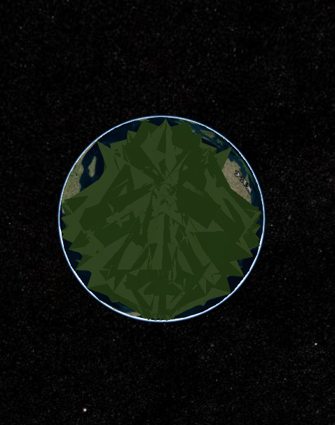
3?There is the strange result, I do not know how to describe......
I encountered similar problems when I generated 3d tiles using other file formats.I tried to redefine the position of the model in cesium and I successfully redefined the official 3d tiles provided by cesium.Unfortunately, it does not work for the 3d tiles that I generate, maybe because of the coordinate system or anything else I do not know.

This is not what I'm good at, so the problems I've encountered may be small cases for you.I can provide a correct COLLADA file, I hope FME official can successfully turn into 3d tiles and can be displayed normally in cesium.If you succeed, I hope you can tell me what is wrong and how to solve it.

Thanks a lot!

In addition, I used Blender exported COLLADA file to generate 3d tiles.When loaded in cesium, the system throws an error: can not find the corresponding json file (very strange problem).

Best answer by takashi

Hi @zhengsy, as I mentioned before, I suppose the reason is that you haven't set an appropriate coordinate system to the dataset before writing it into Cesium 3D Tiles file.

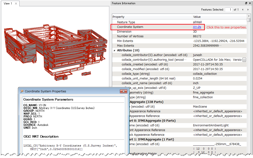
Although FME doesn't support reading Cesium 3D Tiles dataset, you can read the source COLLADA dataset with FME and see its details with Feature Information window in FME Data Inspector. Take a closer look at the source dataset always if you couldn't get your desired result.

  1. As you can see above, the units of distance is inches. Probably you will have to convert it to an appropriate units (e.g. meters) for the target coordinate system. The Scaler can be used to do that (for example, multiply X, Y, and Z by 0.0254 to convert inches to meters).
  2. Next, move the feature to the correct location in the target coordinate system. You have to know the origin (0, 0) of the local coordinate system has to be mapped to what coordinates (x, y) in the target coordinate system. You can use the Offsetter transformer (Mode: Cartesian Coordinates).
  3. You can then set the target coordinate system to the feature with the CoordinateSystemSetter before writing.

Anyway, you will have to know the (x, y) in the target coordinate system corresponding to the origin (0, 0) in the local coordinate system of the source data. Also, in some cases, a CAD data may have been rotated around a point. If the data is rotated, you will also have to know the rotation angle and the center coordinates of the rotation, and modify the axis direction with the Rotator transformer.

View original
Did this help you find an answer to your question?

takashi
Contributor
Forum|alt.badge.img+17
  • Contributor
  • November 29, 2017

Hi @zhengsy, as I mentioned before, I suppose the reason is that you haven't set an appropriate coordinate system to the dataset before writing it into Cesium 3D Tiles file.

Although FME doesn't support reading Cesium 3D Tiles dataset, you can read the source COLLADA dataset with FME and see its details with Feature Information window in FME Data Inspector. Take a closer look at the source dataset always if you couldn't get your desired result.

  1. As you can see above, the units of distance is inches. Probably you will have to convert it to an appropriate units (e.g. meters) for the target coordinate system. The Scaler can be used to do that (for example, multiply X, Y, and Z by 0.0254 to convert inches to meters).
  2. Next, move the feature to the correct location in the target coordinate system. You have to know the origin (0, 0) of the local coordinate system has to be mapped to what coordinates (x, y) in the target coordinate system. You can use the Offsetter transformer (Mode: Cartesian Coordinates).
  3. You can then set the target coordinate system to the feature with the CoordinateSystemSetter before writing.

Anyway, you will have to know the (x, y) in the target coordinate system corresponding to the origin (0, 0) in the local coordinate system of the source data. Also, in some cases, a CAD data may have been rotated around a point. If the data is rotated, you will also have to know the rotation angle and the center coordinates of the rotation, and modify the axis direction with the Rotator transformer.


Forum|alt.badge.img
  • November 29, 2017
takashi wrote:

Hi @zhengsy, as I mentioned before, I suppose the reason is that you haven't set an appropriate coordinate system to the dataset before writing it into Cesium 3D Tiles file.

Although FME doesn't support reading Cesium 3D Tiles dataset, you can read the source COLLADA dataset with FME and see its details with Feature Information window in FME Data Inspector. Take a closer look at the source dataset always if you couldn't get your desired result.

  1. As you can see above, the units of distance is inches. Probably you will have to convert it to an appropriate units (e.g. meters) for the target coordinate system. The Scaler can be used to do that (for example, multiply X, Y, and Z by 0.0254 to convert inches to meters).
  2. Next, move the feature to the correct location in the target coordinate system. You have to know the origin (0, 0) of the local coordinate system has to be mapped to what coordinates (x, y) in the target coordinate system. You can use the Offsetter transformer (Mode: Cartesian Coordinates).
  3. You can then set the target coordinate system to the feature with the CoordinateSystemSetter before writing.

Anyway, you will have to know the (x, y) in the target coordinate system corresponding to the origin (0, 0) in the local coordinate system of the source data. Also, in some cases, a CAD data may have been rotated around a point. If the data is rotated, you will also have to know the rotation angle and the center coordinates of the rotation, and modify the axis direction with the Rotator transformer.

@takashi


Thank you very much for your answer and It helps me a lot.


If I know the (x, y) in the target coordinate system corresponding to the origin (0, 0) in the local coordinate system of the source data. How do I move the feature to the correct location in the target coordinate system. Now I use Offsetter transformer to move the feature.I want to know there are other ways? If not, does FME provide the transformation between different coordinate systems? Because FME provides a very large number of coordinate system, and the division is very detailed.


For example, I know the (x, y) of Beijing in the WGS84 coordinate system, and I want to know the position in the DGN95.UTM-50N coordinate system. Can FME do a job like this? My conversion between coordinate systems is not very good, especially when the coordinate system is divided so meticulous.If FME can help me, it will save me a lot of time.


Sincere thanks to you, my friend.

takashi
Contributor
Forum|alt.badge.img+17
  • Contributor
  • November 29, 2017
takashi wrote:

Hi @zhengsy, as I mentioned before, I suppose the reason is that you haven't set an appropriate coordinate system to the dataset before writing it into Cesium 3D Tiles file.

Although FME doesn't support reading Cesium 3D Tiles dataset, you can read the source COLLADA dataset with FME and see its details with Feature Information window in FME Data Inspector. Take a closer look at the source dataset always if you couldn't get your desired result.

  1. As you can see above, the units of distance is inches. Probably you will have to convert it to an appropriate units (e.g. meters) for the target coordinate system. The Scaler can be used to do that (for example, multiply X, Y, and Z by 0.0254 to convert inches to meters).
  2. Next, move the feature to the correct location in the target coordinate system. You have to know the origin (0, 0) of the local coordinate system has to be mapped to what coordinates (x, y) in the target coordinate system. You can use the Offsetter transformer (Mode: Cartesian Coordinates).
  3. You can then set the target coordinate system to the feature with the CoordinateSystemSetter before writing.

Anyway, you will have to know the (x, y) in the target coordinate system corresponding to the origin (0, 0) in the local coordinate system of the source data. Also, in some cases, a CAD data may have been rotated around a point. If the data is rotated, you will also have to know the rotation angle and the center coordinates of the rotation, and modify the axis direction with the Rotator transformer.

If you know the (x, y) in DGN95.UTM-50N that matches the (0, 0) in the local coordinate system, you can move the feature with the Offseter (X Offset = x, Y Offset = y). Then, set the coordinate system "DGN95.UTM-50N" to the feature with the CoordinateSystemSetter transformer. That's it. (except if the feature has been rotated)


I expect the Cesium 3D Tiles writer could write the feature on the correct location automatically, if the feature had a proper coordinate system which FME can recognize.


takashi
Contributor
Forum|alt.badge.img+17
  • Contributor
  • November 29, 2017
takashi wrote:
If you know the (x, y) in DGN95.UTM-50N that matches the (0, 0) in the local coordinate system, you can move the feature with the Offseter (X Offset = x, Y Offset = y). Then, set the coordinate system "DGN95.UTM-50N" to the feature with the CoordinateSystemSetter transformer. That's it. (except if the feature has been rotated)


I expect the Cesium 3D Tiles writer could write the feature on the correct location automatically, if the feature had a proper coordinate system which FME can recognize.


[Addition] I assumed that the units of length in both DGN95.UTM-50N and the local coordinate system is meters.


Reply


Cookie policy

We use cookies to enhance and personalize your experience. If you accept you agree to our full cookie policy. Learn more about our cookies.

 
Cookie settings