Question

Offset, scale and rotate using set X&Y coordiantes


chrbalm
Contributor
Forum|alt.badge.img+8

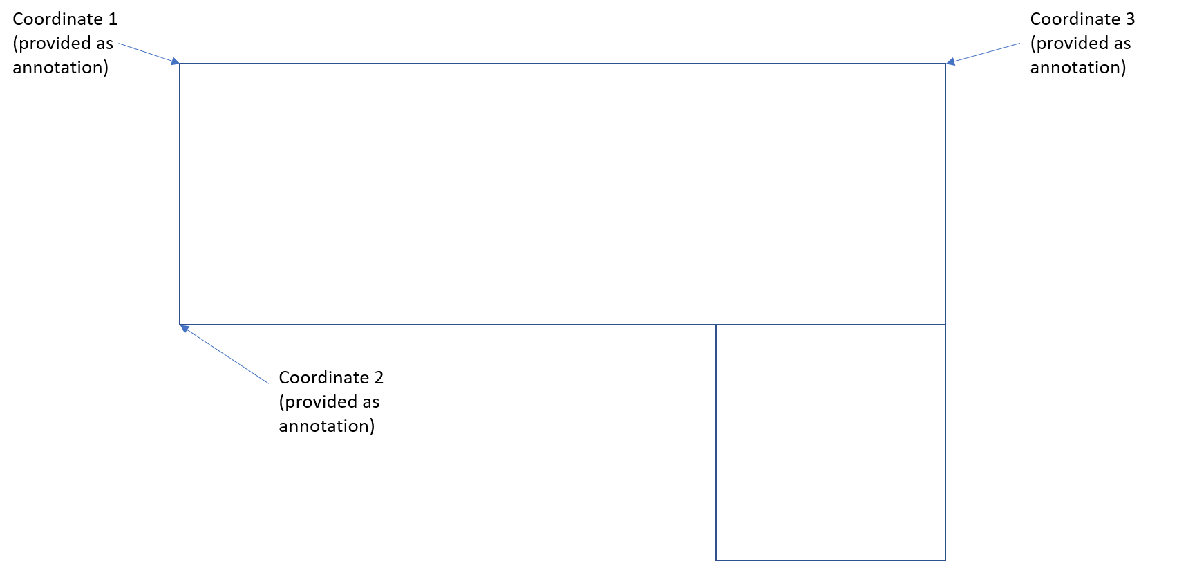
I have several DWGs, all of which have not been spatially coordinated, however each has 3 set points with an annotation referring to the National Grid X&Y.

I am essentially trying to understand if I can take these 3 points and assign the National Grid coordinates provided as the annotation?

7 replies

caracadrian
Contributor
Forum|alt.badge.img+23
  • Contributor
  • March 26, 2021

Use AffineWarper with Control input as 3 lines with first vertex in your original location and second vertex at the specified location from annotation.

https://docs.safe.com/fme/2021.0/html/FME_Desktop_Documentation/FME_Transformers/Transformers/affinewarper.htm


chrbalm
Contributor
Forum|alt.badge.img+8
  • Author
  • Contributor
  • March 26, 2021

Thanks! - Most appreciated for your reply.


I have taken this and attempted it myself. My understanding is that I need to create 3 lines representing the offset of the 3 XYx from where they are currently being drawn to the exact location. I then input this linear feature in as the "Control".

However there doesn't seem to be an corrected output?


It may be the fact that the DWGs I am dealing with are actually linear (I am looking at moving building flood plans) - example below.


Picture1 

1


caracadrian
Contributor
Forum|alt.badge.img+23
  • Contributor
  • March 26, 2021
cbalmbra1 wrote:

Thanks! - Most appreciated for your reply.


I have taken this and attempted it myself. My understanding is that I need to create 3 lines representing the offset of the 3 XYx from where they are currently being drawn to the exact location. I then input this linear feature in as the "Control".

However there doesn't seem to be an corrected output?


It may be the fact that the DWGs I am dealing with are actually linear (I am looking at moving building flood plans) - example below.


Picture1 

1

Can you provide some sample data?

Maybe you have some weird feature types that don't get processed.


chrbalm
Contributor
Forum|alt.badge.img+8
  • Author
  • Contributor
  • March 26, 2021

DWG attached. I've had to remove most of the data, but should give you an idea.

Thanks again.


chrbalm
Contributor
Forum|alt.badge.img+8
  • Author
  • Contributor
  • March 29, 2021
caracadrian wrote:

Can you provide some sample data?

Maybe you have some weird feature types that don't get processed.

Apologies. I keep forgetting to "Reply" rather than to create another comment. DWG attached below


caracadrian
Contributor
Forum|alt.badge.img+23
  • Contributor
  • March 29, 2021
cbalmbra1 wrote:

DWG attached. I've had to remove most of the data, but should give you an idea.

Thanks again.

I looked at your sample data. The destination coordinates are wrong. I can't get something normal even manually. I don't think you are trying a Mobius inversion 😃

AffineWarper assumes a 3D operation and needs 4 sets of points. You can try RubberSheeter or figure out the math and do Offseter, Rotator and Scaler.

But first, get some correct data.


chrbalm
Contributor
Forum|alt.badge.img+8
  • Author
  • Contributor
  • March 31, 2021
caracadrian wrote:

I looked at your sample data. The destination coordinates are wrong. I can't get something normal even manually. I don't think you are trying a Mobius inversion 😃

AffineWarper assumes a 3D operation and needs 4 sets of points. You can try RubberSheeter or figure out the math and do Offseter, Rotator and Scaler.

But first, get some correct data.

Thanks. I modified the original DWG to ensure it sits in the correct location @ OS, so just a simple extraction workbench.

Thanks again :)


Cookie policy

We use cookies to enhance and personalize your experience. If you accept you agree to our full cookie policy. Learn more about our cookies.

 
Cookie settings