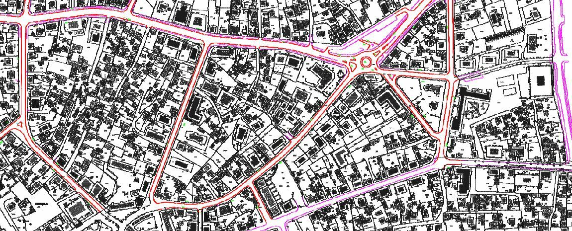
I am trying to do a rasterization of one DWG. After I run MapnikRasterizer, I get good results for most of the parameters but TEXT is problematic. In AutoCAD my text looks like this:
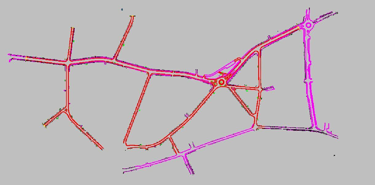
But when I get a result text looks like this:
I have tried setting almost all options in MapnikRasterizer. I have turned on in writers attributes "autocad_text_rotation" and tried to enable it in Mapnik, but I get an error. Does anybody have an idea how to preserve text same as in CAD?
Thank You in advance!
Best answer by lenaatsafe
Hi @maliodpalube
to preserve the original DWG texts as they are, you might want to use TextStroker to convert the texts into polygons first and then style them with MapnikRasterizer Polygon Symbolizer. When you use Text Symbolizer, you create the text from scratch based on the feature attributes and symbolizer parameters.
This post is closed to further activity.
It may be an old question, an answered question, an implemented idea, or a notification-only post.
Please check post dates before relying on any information in a question or answer.
For follow-up or related questions, please post a new question or idea.
If there is a genuine update to be made, please contact us and request that the post is reopened.
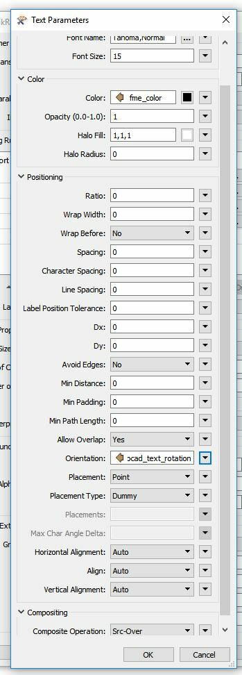
What kind of error are you getting? I have used the text in Mapnik before and didn't see an issue. I used the orientation parameter to rotate the text
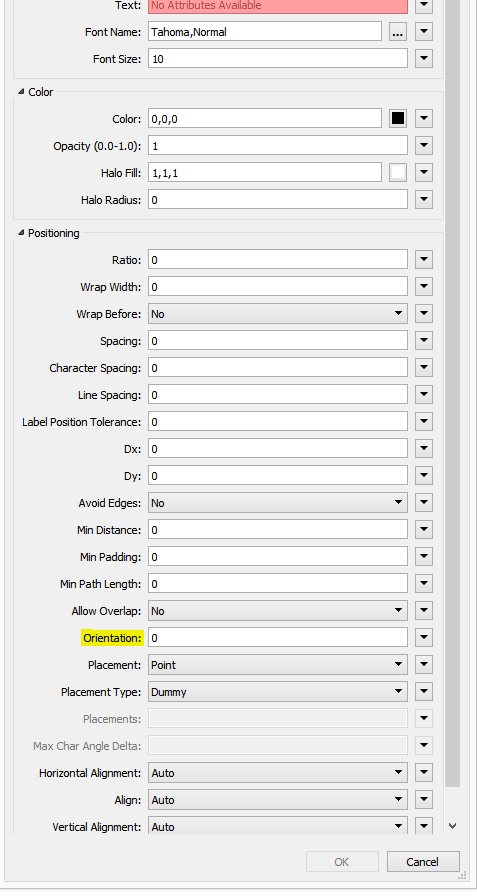
Here is how my settings for Text looks. I don't know why I am getting an error because it should preserve text rotation from AutoCAD.
MapnikRasterizer_<Rejected>(TeeFactory): MapnikRasterizer_<Rejected>: Termination Message: 'MapnikRasterizer output a <Rejected> feature. To continue translation when features are rejected, change 'Workspace Parameters' > Translation > 'Rejected Feature Handling' to 'Continue Translation''
MapnikRasterizer_<Rejected>: Termination Message: 'MapnikRasterizer output a <Rejected> feature. To continue translation when features are rejected, change 'Workspace Parameters' > Translation > 'Rejected Feature Handling' to 'Continue Translation''
Stored 1 feature(s) to FME feature store file `C:\\Users\\ddeja\\AppData\\Local\\Temp\\no-conn-ffs-1517228103358_11232.ffs'
What kind of error are you getting? I have used the text in Mapnik before and didn't see an issue. I used the orientation parameter to rotate the text
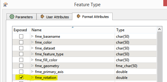
I didn't do anything different except I had exposed the fme_rotation on the reader and used this in the orientation field. I also used fme_text_string as my Text parameter . I dont see why this would of made a difference though
I think the reason why autocad_text_rotation wasn't working is because it may have been empty/missing. You can double check this in the FME Data Inspector in the Feature Information Window on the right. Typically autocad_rotation (which is translated into fme_rotation) would be used. For the text height you should base it off of autocad_height. You may need to experiment with a text scaling factor so that you get a nicer output. The autocad_height attribute will be in what ever units the Coordinate System is in (feet or meters). You will need to get a value that looks good in pixels. Here is a little more information on Autocad text in FME - You can also check out the text entity specific documentation to see the various attribute values.
I think the reason why autocad_text_rotation wasn't working is because it may have been empty/missing. You can double check this in the FME Data Inspector in the Feature Information Window on the right. Typically autocad_rotation (which is translated into fme_rotation) would be used. For the text height you should base it off of autocad_height. You may need to experiment with a text scaling factor so that you get a nicer output. The autocad_height attribute will be in what ever units the Coordinate System is in (feet or meters). You will need to get a value that looks good in pixels. Here is a little more information on Autocad text in FME - You can also check out the text entity specific documentation to see the various attribute values.
I have successfully preserve rotation of text by fme_rotation, @pretap helped me. I am still fighting to keep the size of text because there is probably some kind of bug or what. When I enter the value 11*@Value(fme_text_size) it gives me almost good result, also, when I enter 9*@Value(fme_text_size) I also get almost good result and it is obvious that 10* would be the best solution but when I enter that I get so small numbers that it is obvious that it is some kind of error. Also, it would be useful for me if I would be able to preserve Italic style of numbers but also I am not sure how to do it.
At this point, I have succeeded to make a raster but I am facing a few problems. Text size is not so important so I can put that on the side. I have figured out how to solve rotation of the text. My biggest problem is how to save position of text because it seems that it is displaced. At Mapnik settings there is an option for dX and dY. I have tried to load autocad_text_position_x and autocad_text_position_y in that file but there is an error then but that was expected since those values probably present the displacement on each axis. I have tried to enter some random values in that field, first I've tried with dx = 1 and dy = 0 and later 1;1 and 1;2 and 1;5 and etc and I figured out that the movement is not regular since it appears not to be like it should and if I set dx=2 it doesn't even move the numbers on same size as dx=1. After an advice of @pretap I have tried by setting the offsetter in my workbench and changing those values but again no good result happened.
I am trying to figure out what could be the problem but it is not going well. Can I get any feedback?
Text is always the most tricky thing in my opinion. There are just so many options and tweaks to make. I applaud you on your determination to get it right and I'm sorry to hear that your having to battle with it.
Getting the position of Text Features right is fairly tricky for FME and coming from AutoCAD only complicates it further I'm afraid. The first thing to do is check to see what the text look like in the FME Data Inspector compared to AutoCAD. There are a number of AutoCAD attributes the FME doesn't account for in it's rendering process. For example; Italics/Oblique factor and font. Another important one is justification. You can read more about justification in FME here.
Here is the documentation on how FME represents AutoCAD text entities. You could compare these attributes to what is listed in the FME Data Inspector Feature Information window when a text entity is selected.
I think using the dx and dy is a good option here to tweak positions, although I'm a little concerned at what you've found in your testing. It is important to remember that the offsets here (dx/dy), with the rasterizer, are measured in pixels/cells and either typically meters or feet in the Data Inspector (depends on your projection). The same goes for font size. What would really help you is if you can calculate the size of a pixel/cell in relation to the AutoCAD unit/scale. This should help in calculating the values which need to be set.
Here is the link to the Mapnik documentation which contains a little more information on what each of the text settings do. Perhaps the Horizontal and Vertical Alignment values can be set to match what the justification setting are in AutoCAD.
I think you're on the right track here but it is hard going for sure.
The text read from AutoCAD (and Microstation as well) will always be bottom left justified, regardless of the contents of autocad_justification. This is how the geometry is stored in the DWG file.
FME will also attempt to calculate the original placement point of the text, storing this location in the attributes autocad_alignment_x, .y, .z. This location is calculated using the text size, but not the font metrics, and so is not the exact placement location.
In the MapnikRasterizer, please set the Horizontal Alignment for the text to Right and the Vertical Alignment to Top. This seems to be the equivalent of AutoCAD's Left Bottom.
The MapnikRasterizer can only use TrueType fonts installed on your system. If you have AutoCAD installed, TrueType versions of the AutoCAD fonts will have been installed as well, but if not, you will need to choose alternatives.
The size of the text font is based on pixels, so you need to have a multiplier applied to the AutoCAD text size, based on the output raster resolution. The best multiplier seems to be the number of pixels per unit (feet/meter - whichever you are using).
Thank You for an answer. I am trying still to fix this, it is going hard but I hope that I will be able to fix it.
Now I am facing another problem.
My raster needs to be transparent and I have set RGBA so I can set 4th layer value =0 and background to black so I have transparent image.
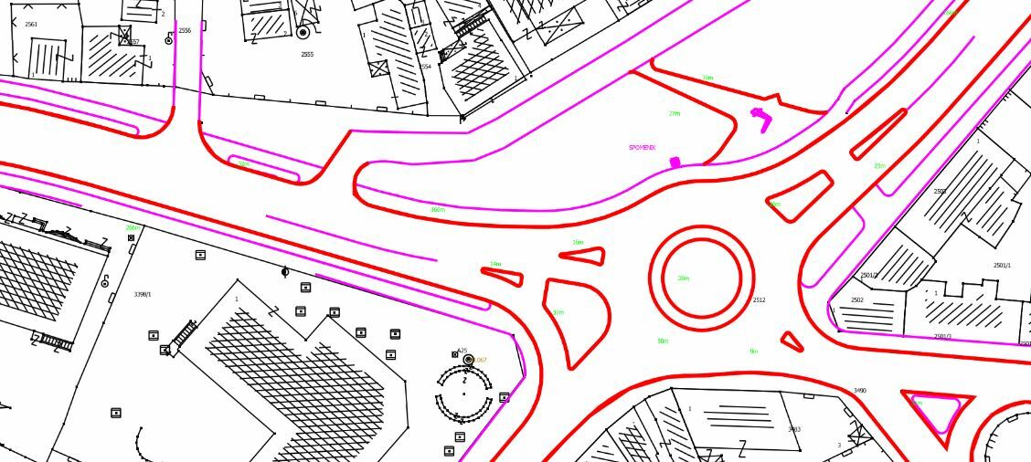
Problem is that only things that are in other color then black are shown.
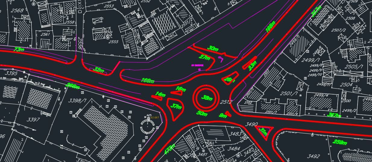
I am attaching You how does it look. When I open it in FME Data Inspector I can see everything but when I open in other Image viewer I see only things that are not black.
Thank You for an answer. I am trying still to fix this, it is going hard but I hope that I will be able to fix it.
Now I am facing another problem.
My raster needs to be transparent and I have set RGBA so I can set 4th layer value =0 and background to black so I have transparent image.
Problem is that only things that are in other color then black are shown.
I am attaching You how does it look. When I open it in FME Data Inspector I can see everything but when I open in other Image viewer I see only things that are not black.
What could cause this problem?
Hi @maliodpalube
What format are you saving the image out to? Some formats may not support RGBA imagery.
to preserve the original DWG texts as they are, you might want to use TextStroker to convert the texts into polygons first and then style them with MapnikRasterizer Polygon Symbolizer. When you use Text Symbolizer, you create the text from scratch based on the feature attributes and symbolizer parameters.


")