I want to create simple mesh trees from Point Cloud (LIDAR) in FME.
And the closest thing I came to was with the "PointCloudSurfaceBuilder" transformer.
Can anybody help me with this, please.
The file is the way I want the final trees look like (it seems like it is about 8 piece of pentagon polygons for each tree).
And the file is the closest I came in FME.
I attach the FME-Workbench file and the input LAS file (and it looks like this ).
Best regards,
Jonas
Best answer by redgeographics
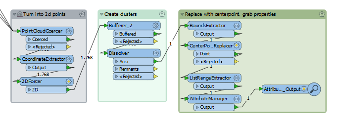
If you turn the point cloud into individual points (PointCloudCoercer) you can buffer/dissolve them to create an outline that more or less confirms to the tree shape. Using a CoordinateExtractor before the buffering gives you the coordinate values, you can then have the Dissolver create a list of the z-values and use a ListRangeExtractor to get the min and max height out of the tree. For the diameter it's a bit trickier but getting the bounds from the tree shape (minus a bit to account for the buffering) and then get the average of the x and y difference should give you a relatively accurate estimate (unless the tree is awkwardly shaped). From there you could start building your idealised version.
I don't usually work with AutoCAD so I'm not sure either how a block would be used, but it sounds like a viable approach.
Your point cloud is waaaaaay too detailed. You could try thinning it (PointCloudThinner) but I doubt you'd get to the desired result.
One idea I had when I was looking into this a while ago was try and represent a tree by several stacked cylinders. So at x cm vertical intervals lump the points together (buffer them and dissolving the buffers, find all points that intersect the buffer and create a hull for those, determine the diameter of the hull and then place a cylinder with that diameter and thickness centered on the centerpoint. Still clunky but it might just work. I don't think I have a workspace that shows that though.
If you turn the point cloud into individual points (PointCloudCoercer) you can buffer/dissolve them to create an outline that more or less confirms to the tree shape. Using a CoordinateExtractor before the buffering gives you the coordinate values, you can then have the Dissolver create a list of the z-values and use a ListRangeExtractor to get the min and max height out of the tree. For the diameter it's a bit trickier but getting the bounds from the tree shape (minus a bit to account for the buffering) and then get the average of the x and y difference should give you a relatively accurate estimate (unless the tree is awkwardly shaped). From there you could start building your idealised version.
I don't usually work with AutoCAD so I'm not sure either how a block would be used, but it sounds like a viable approach.
I have tested your suggestion now and it worked great but I cannot figure out the last part that replace the centerpoint with a symbol that I can scale in size (I tried the Pointstyler without success).
Is there someone else out there how can help with this?
If you turn the point cloud into individual points (PointCloudCoercer) you can buffer/dissolve them to create an outline that more or less confirms to the tree shape. Using a CoordinateExtractor before the buffering gives you the coordinate values, you can then have the Dissolver create a list of the z-values and use a ListRangeExtractor to get the min and max height out of the tree. For the diameter it's a bit trickier but getting the bounds from the tree shape (minus a bit to account for the buffering) and then get the average of the x and y difference should give you a relatively accurate estimate (unless the tree is awkwardly shaped). From there you could start building your idealised version.
I don't usually work with AutoCAD so I'm not sure either how a block would be used, but it sounds like a viable approach.
We use 3 different kinds of cookies. You can choose which cookies you want to accept. We need basic cookies to make this site work, therefore these are the minimum you can select. Learn more about our cookies.