Hello all, very new user here. New to FME, point clouds, LiDAR, and all related.


I'm having an issue where a LiDAR scan I'm attempting to visualize is only displaying correctly when I select 2D in the FME Data Inspector. So when I load the file in to FME, the following is displayed (I've panned and zoomed to make it more obvious what is going on):
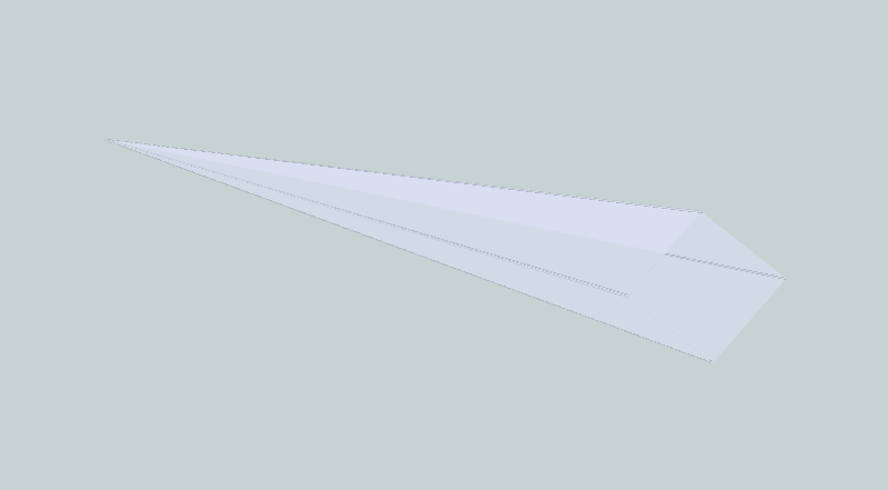
There is nothing but a long thin line even though the inspector recognizes I have loaded > 8 million points. However, when I switch to 2D (the button on the toolbar at the top), the following displays:
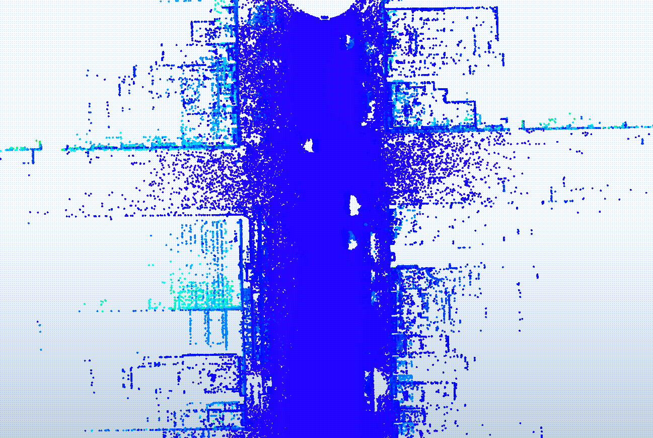
This is in line with what I was expecting, a road with corners and holes in the road where the scanning vehicle passed cars. But again, it only displays like this in 2D.

I understand this is likely a scan format issue. This scan is stored in a polar format based on WGS84, so I attempted to convert it to an XYZ format with a python algorithm a friend suggested to me. At first I thought it had worked, but that one was distorted also. Here is what happened when I loaded that xyz file into Data Inspector:

(street from the front)
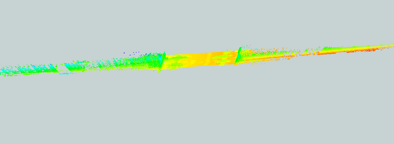
(street from the top)

Somewhere in the conversion, the cloud got squished along the dimension of the street. I really am not sure what is going on here or what to make of the results I'm getting. Here is some additional information from the Inspector on both the LAS file and the XYZ file:
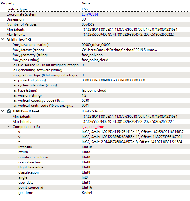
(las)
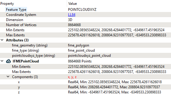
(xyz)

Any help or ideas would be greatly appreciated.

Hi @samgolden00

I see the coordinate system is LL84 on one and LL-WGS84 on the other. Use a BoundingBoxAccumulator to create a boundingbox of the features - there might be some points along 0,0 or something that breaks the viewer. You can also try to view the las file at http://plas.io/ to see how it looks.


It looks like you have a point or some points that have incorrect z values. If you calculate min and max statistics you might be able to identify the erroneous values and then filter them out


Hi @samgolden00,

Any 3D data in lat/long coordinates will have a distorted 3D display in the Data Inspector. This is due to the XY values having a much larger unit (degree) than the Z values (meter), so the point cloud will be stretched out along the Z axis.

To get a better look at the data in 3D, please create a simple workspace to read the point cloud, then add a CsmapReprojector transformer to reproject the cloud to SPHERICAL_MERCATOR (or another projected coordinate system). Connect the CsmapReprojector output to an Inspector transformer, then run the workspace to view the point cloud.


I have 3d point cloud data but my data is allocated only in 2 axis that are Z and Y, so i want to drop the x axis and convert that into 2d image wanted to find the edges. after finding the edges in 2d can i again regain the droped axis.


I have 3d point cloud data but my data is allocated only in 2 axis that are Z and Y, so i want to drop the x axis and convert that into 2d image wanted to find the edges. after finding the edges in 2d can i again regain the droped axis.

Hi @nishmithaj26​,

Please try using the CoordinateSwapper transformer to swap the Z and X coordinates, then the NumericRasterizer to convert to an image.


Reply