Hi, 


I am trying to connect transmission lines to POIs using the PointonLineOverlayer but before that i wanted to dissolve all the transmission lines into a singular line/polyline.


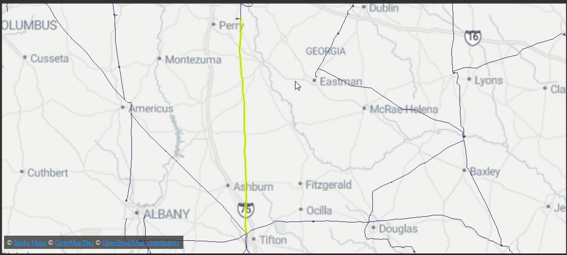
The issue I am having is that regardless of what I try I am getting breaks in the lines where there isn’t supposed to be any like in the image below. 


I am trying to use a combination of the generalizer, snapper, intersector, and linecombiner transformers but these breaks still persist. I even tried to buffer the lines, dissolve and then use centerline replacer and they persisted.


Would appreciate any advice on this manner.
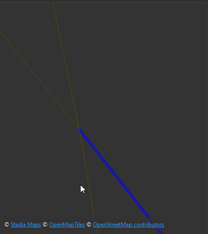
 

The Intersector will break lines where they intersect, so that may be part of your problem.

Have you tried using the LineCombiner without the Intersector?


The Intersector will break lines where they intersect, so that may be part of your problem.

Have you tried using the LineCombiner without the Intersector?

Hi, thanks for the quick response! That was my original attempt but I was still getting the different segments. I tried to use the Intersector incase multiple lines overlapped and was causing issues


Do all of these lines connect and they need to actually be one line? Or do you just need one feature in fme with a set of attributes to run against the points? If the latter, you could run them through an Aggregator grouping by the attributes that you want. 


Do all of these lines connect and they need to actually be one line? Or do you just need one feature in fme with a set of attributes to run against the points? If the latter, you could run them through an Aggregator grouping by the attributes that you want. 

They don’t all connect, there’s parts where a transmission line doesn’t connect to the rest of the network. There’s no common attribute to group them by as I have already filtered to just the lines I need (230 kV). When using the aggregator (without group processing) I do get a single feature but once I use the pointonlineoverlayer the extra segments appear again. I am thinking there’s a self-intersection issue but can’t seem to resolve it


When you use the PointOnLineOverlayer it will split the lines where they intersect with the points. If you want to maintain the single feature from the aggregator after relating to the points, then you may need another transformer than the PointOnLineOverlayer. Are you trying to filter out your points to those that intersect the network? Do you need the line(s) after you relate them to the points?


When you use the PointOnLineOverlayer it will split the lines where they intersect with the points. If you want to maintain the single feature from the aggregator after relating to the points, then you may need another transformer than the PointOnLineOverlayer. Are you trying to filter out your points to those that intersect the network? Do you need the line(s) after you relate them to the points?

Sorry, yes I am aware that the PointonLineOverlayer will split the lines where it intersects with the points, which is exactly what I want to happen but there are breaks in the lines after using the PointsonLineOverLayer where there aren’t any points from the POI layer.

The end goal is to have each 230kv transmission line with attributes for the start and end POI values so I would need the lines after relating them


So after you relate the lines to the POIs, you will want to have multiple lines each running from 1 start to 1 finish point. And you then only want the lines that are directly connecting a start and finish? For the lines that you said don’t connect to the rest those will be excluded or at least separate?


So after you relate the lines to the POIs, you will want to have multiple lines each running from 1 start to 1 finish point. And you then only want the lines that are directly connecting a start and finish? For the lines that you said don’t connect to the rest those will be excluded?

Correct, for lines that don’t connect to the the rest, as long as they connect to a start and finish point they can remain but for the purposes of troubleshooting I can omit those for the time being


Here’s an example of a line connecting to a start and end point that I would want as its own line 


Okay, it might be better to tackle this from another direction then. You may want to start by using a TopologyBuilder and NetworkTopologyCalculator. This may be helpful in cleaning up the lines. You can then use the ShortestPathFinder to identify which paths are needed between the start and end points (you may need to group this by an attribute so it knows which start to which end). And then once you have those lines pathed you could use a LineCombiner grouped by them, or grouped Aggregator.


Okay, it might be better to tackle this from another direction then. You may want to start by using a TopologyBuilder and NetworkTopologyCalculator. This may be helpful in cleaning up the lines. You can then use the ShortestPathFinder to identify which paths are needed between the start and end points (you may need to group this by an attribute so it knows which start to which end). And then once you have those lines pathed you could use a LineCombiner grouped by them, or grouped Aggregator.


Giving that a try but I can’t seem to get it to work.

Are you able to share a sample of your dataset and workspace in a template perhaps? I am off traveling for a couple days but will be back Monday and can take a look if you have not figured it out yet. Perhaps someone else may also have an idea on another solution.

I have attached a zip file with the template, transmission lines and POI layer, thank you again for all the advice so far, I really do appreciate it!


I have attached a zip file with the template, transmission lines and POI layer, thank you again for all the advice so far, I really do appreciate it!

Unfortunately attachment does not include source files. Eg.


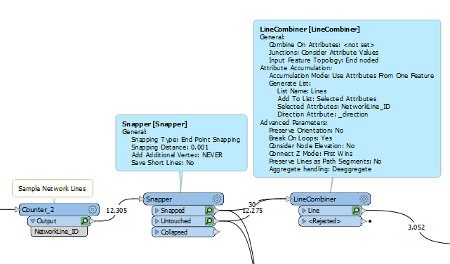
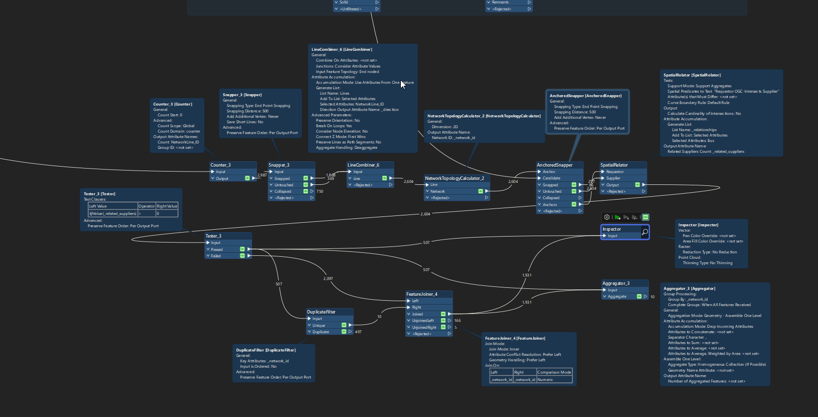
At the risk of oversimplifying it, but this sample gives me combined lines on our own transmission network.   As long as the topology is End-Noded.


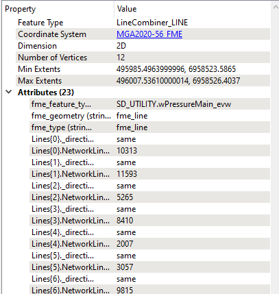
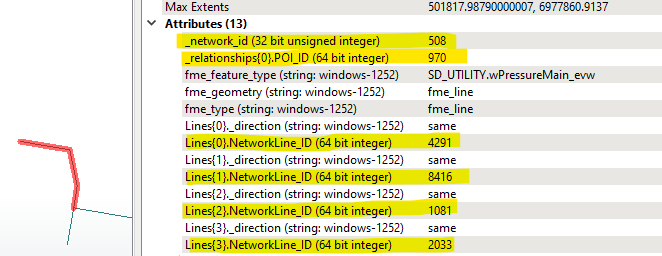
Eg. Example combined line that only breaks where Topology has 3 edges or more coming into the same node.  In this example LineCombiner feature output,  It took 7 source lines and combined them into 1, and kept their original ID in the optional LineCombiner output List.


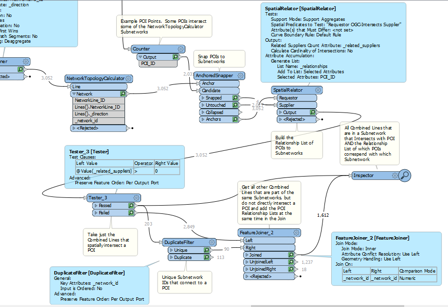
If only want the part of the network that is connected to POI +  figure out which Subnetworks are a Group of Edges connecting to a POI, then from the LineCombiner, this further becomes:


From the Inspector, if want to Aggregate Further, can just use an extra Aggregator  , with Group By set to _network_id

The key to this is to establish the Relationship output with SpatialRelator……….not PointOnLineOverLayer.

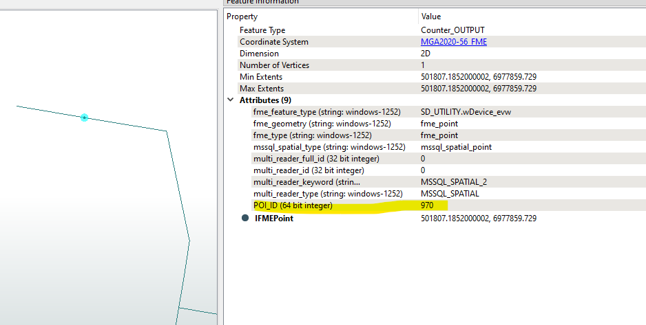
The output from this also gives all the Topological Data:  Source Line IDs vs Subnetwork IDs vs POI IDs that intersect with those Subnetworks.  These can be separately be tabulated as a Source Line vs SubNetwork vs POIs on SubNetwork Topology table by using multiple ListExploders


I have attached a zip file with the template, transmission lines and POI layer, thank you again for all the advice so far, I really do appreciate it!

Unfortunately attachment does not include source files. Eg.


Sorry the file called “Transmission Lines” in the zip is the replacement for that file, I am going to give your advice a try later today and will let you know how it went


Sorry the file called “Transmission Lines” in the zip is the replacement for that file, I am going to give your advice a try later today and will let you know how it went

I thought that could possibly be the case, however the Transmission Lines SHP file only contains one polyline, so it isn’t possible to build a general solution from that sample for networks that have potentially crossing lines and lines that have node topology where polyline vertices have common coordinates to other separate lines.  So, just used our utility network instead for the sample.

My apologies, it seems like I saved a single feature by accident, this folder should have the correct transmission lines now!

I tried your solution and it gave reasonable results but the issue is I need each transmission line to be a singular line connecting 1 POI to another POI. When using this method it retains the the broken transmission lines that should have been dissolved/joined into one. When aggregating it by network ID, it gives me larger polylines that contain multiple transmission lines which isn’t my end goal either. 


My end result would ideally be individual transmission lines with attributes for the starting bus and ending bus numbers for each line. If 2 busses are connected by 4 segments then these 4 segments should be one transmission line, not sure if I explained it well.


Are there any attributes available for the points that would link 2 points together? As in, is there a way to know that any given 2 points should be a start and finish of the same line?


Are there any attributes available for the points that would link 2 points together? As in, is there a way to know that any given 2 points should be a start and finish of the same line?

Unfortunately no, as a work around I have been manually doing it in QGIS by splitting the lines and then merging lines segments into singular lines to connect transmission lines visually. Separating or duplicating features where I need them as well.


It doesn’t seem to be something that can be automated, but I could be wrong.


Okay, I am trying to combine your buffering/dissolve/centerlinereplacement method as a lot of these lines do not connect which makes things tricky, going to feed that into a couple ideas I have with networks and will see what I can do. I understand the struggle though, you may not believe it but the average data quality I work with is worse.


Okay, I am trying to combine your buffering/dissolve/centerlinereplacement method as a lot of these lines do not connect which makes things tricky, going to feed that into a couple ideas I have with networks and will see what I can do. I understand the struggle though, you may not believe it but the average data quality I work with is worse.

I just want to say thank you again, I appreciate all the effort you’re going through to help me solve this issue <3 

I got as far as getting a proper end-noded network by moving the POIs onto the  nearest network node, getting other nearby End Nodes to snap to the POIs for proper network connectivity, and also splitting in POIs that were not on an end node but on/nearby a Network Vertex, and also Splitting the Network at Junctions as around the bus-bars in particular these have not been split at the points that Transmission Lines connect to them to create End-to-End Topology.

Unfortunately 90% of the effort here is getting a properly End-Noded, snapped together Topology.  I managed to use the usual Network cleansing techniques to get it to this point but yeah, the data quality of the source data is topologically not good and it reminds me of our network before cleansing it ~10 years ago and can tell you that cleansing the data back at the source makes a HUGE difference to the how much time is needed to write network analysis scripts.  Can have the FMW for it, but I didn’t find time to put comments on it 😕

The missing bit unlikely to complete is to put the Snippers in on the (cleansed) network at the POI nodes to break it into the POI-to-POI Subnetworks for deriving the subnetworks and, optionally, paths between the POIs.


Wow that sounds great, if you can send me the FMW that would be appreciated, do you think with your End to End topology, using the shortest path finder would be a viable solution?


The topology is from OSM and HIFLD data so not the best :/


 @pvmvirus  Reading over bwn‘s solution it appears to be a better solution than what I had working so far, so I am going to hold off fiddling with the data any more. Let me know if you end up needing any more help.


OK, attached FMW.

I don’t think that this Topologically “fixes” everything given the state of the source data.  It assumes that a Network Line is only connected to another Network Line if there is Vertex-Vertex Coincidence, or the Network Line End Node is within a generous Network Line End Node spatial proximity and the Network Edge End is not already connected to something else.  But otherwise, yes 90% of the workspace is given over to just deriving an actual Toplogical Network.

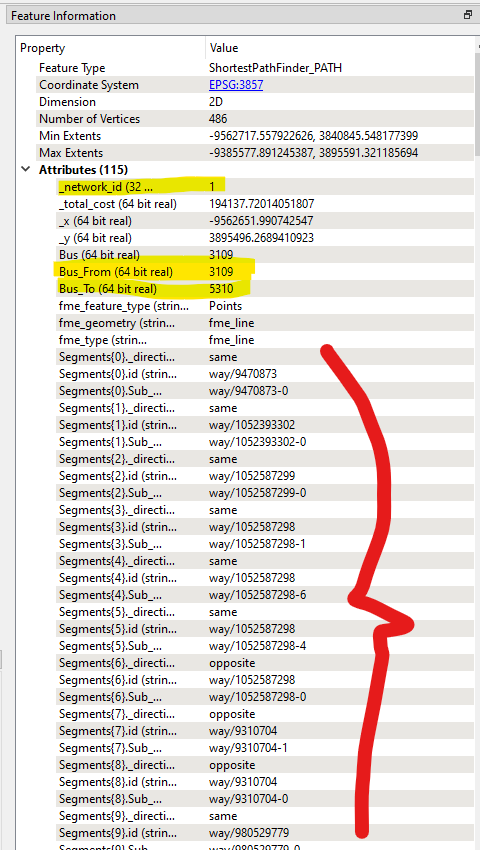
Also put in a concept of Aggregation using ShortestPathFinder but as a general solution it fails if there are multiple paths between a From POI and a To POI on the same subnetwork.   For that I’ve previously posted in InlineQuerier or PythonCaller NetworkX solutions to do an “All Paths” Network Analysis between From and To Nodes, and putting that aside for someone else to look at.


Sample ShortPathFinder results for sample To-From POI Bus Identifiers, with the Segment List of Line IDs and SubIDs (SubIDs have to be used because the original lines need to be broken at Network Junctions which the Source data currently does not do)


Reply