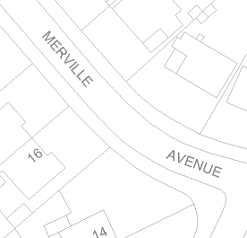
Well, best you can do using the annotation layer is to save the layer to a gdb.
That will "Freeze" it to the placement in the viewing scale.
You can read the layer from the gdb with fme.
That will give you polygons or aggregate polygon, depending on placement. Including a lot of info. like font etc. (alas no height though and no insertion points)
Your example would yield a 2 polygon aggregate. Making it easy to separate them by deaggregaton.
How are you going to give the second bit a new location though.. do you intend to insert a reference point/or line?
In that case you can use a affiner to move the object. The insertion point of the second word is a problem because there is no insertion point stored in the annotation layer.
You could however try to create centerlines and try to filter begin and end of the geometry. Then filter for the resulting corners.
This depends hugely on the way the text "flows".
Full control of placement is better done by having road centerlines, and use segmenting and snipping to create placement locations at will. Of course one would have to have centerlines..
There is tool to convert feature to outline with which you could turn annotation to graphic, but it is under advanced license and has no anti aliasing..
Also you might try adding more spaces...though that's like yuck manual labour.
Thanks @gio we were planning on saving the layer to a gdb to freeze the text placement but yes finding the insertion point and angle of the second word that I imagine is difficult. We haven't played around with it yet as we are trialing a few options. Just trying to gauge whether this is a feasible task. Will let you know if we have any success!
We have access to the tool you mentioned to turn anno to graphic so will take a look at it too thanks.