
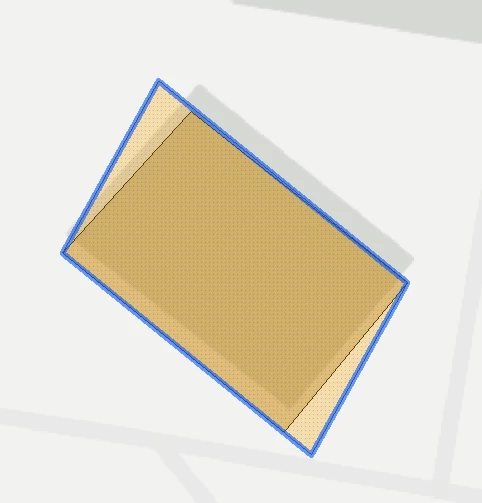
I have a building footprint layer that I am using an oriented bounding box transformer (blue line) and trying to keep the result as close as possible to the original polygon (black line) but for some reason the bounding box is getting squeezed out of shape. 


Does anyone have any suggestions as to why the bounding box is not aligning better?

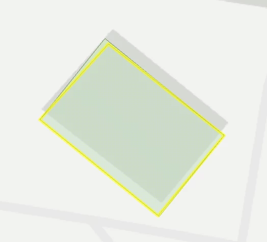
I am using it to try and automate the georeferencing of a CAD drawing and using the AffineWarper with lines that come from the corners of the bounding box. I am using the long side angle in the bounding box to rotate the CAD drawing, which in this example is still correct but the length of the long side is incorrect which puts out the affine points and scale calculation. 


This is a case where the footprint is a basic rectangle but there are many cases where the footprint is an irregular shape.


Still interested to hear of any suitable alternatives but discovered it was a project issue that was causing the misalignment of the bounding box. 


Still not perfect but close


Not sure how complex your challenge is. I have done some “auto” georeferencing of PDF’s before. My process looked like this:

  • Find scale of plot and scale data.
  • Find rotation of plot (north arrow) and rotate data.
  • Select a polygon of the area where the data is supposed to be.
  • For both sets (referenced and to be referenced) create areas from lines, calculate perimeter and area, round to meters.
  • For both sets, keep only unique perimeter / area combinations.
  • Match unique combinations of both sets.
  • Calculate XY displacement of centerpoints of matched areas.
  • Analyse which XY displacement of centerpoints are most common, drop outliers.
  • Use these XY displacement values to move the entire unreferenced set to the referenced set.

A bit brute force method, but it worked quite well for the large amount of PDF plots we received.


Thanks ​@nielsgerrits the approach list is very similar to what I have done as I get the bounding box of the ground floor CAD and bounding box of ground floor GIS and use centre point to align all the other CAD floors, then rotate and scale.  I then create the connection lines from GIS and CAD and using the AffineWarper move all other features. I have found the shift, rotate, scale option pretty good but very slow when there are lots of features (some of my drawings have over 1,000,000 features over 20 floors) so the affine works much quicker. Thanks again for taking the time to reply 


Reply