Question

mosaic and nodata

  • November 19, 2018
  • 3 replies
  • 62 views

marionmahot
Contributor
Forum|alt.badge.img+2

Hello

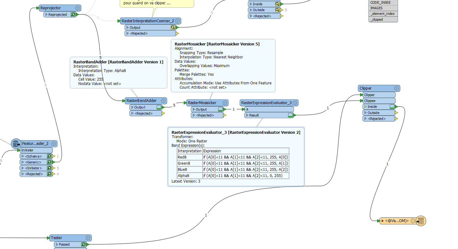
I'm looking for the rasters that are in the same polygon to assemble them and then cut the mosaic according to the polygon.

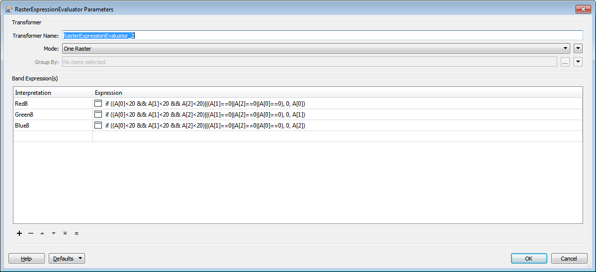
In this treatment I try to remove the black edges of the images to make the mosaic but I still have black pixels.

Thanks


D045_3P_79_4_0001.zip

3 replies

mark2atsafe
Safer
Forum|alt.badge.img+44
  • Safer
  • November 19, 2018

Just taking a look at this now. I do wonder what Clipper_2 is doing. The workspace is still running, but that transformer looks like It clips the raster to the same extents they had before. And you do not have the nodata set on the output because I don't think it inherits that from the Clipper feature. But I will look closer and let you know.


mark2atsafe
Safer
Forum|alt.badge.img+44
  • Safer
  • November 19, 2018

In essence the workspace sort of gives you what you want. The output still has black areas, but you have just set them to zero opacity, so they can't be seen. But it is not the white cells you asked for, and it is not very quick either. So let's look at the workspace in depth.

I don't think the "Pour forme particuliere" part of the workspace does what you think, but that's OK. It took me quite a while to figure out what to do, and in what order (which is important).

That part replaces some colors and sets up nodata, but that information gets lost in the Clipper_2 transformer. But it sort of works because you have set up the Clipper with Preserve Clippee Extents to No, so those parts of the data are clipped away completely, leaving 0,0,0,0 values.

So that is keeping black cells, but making them invisible.

The very simplest way to speed it up would be to put a DonutHoleRemover after the RasterExtentsCoercer. That's because you are coercing the contents into a very, very, very complex donut shape, and using that to clip the raster is (I believe) a long and costly process.

But, to give white cells in a quick way, I think you would:

  • RasterBandAdder (Add an Alpha band, with values 255)
  • RasterMosaicker (Get a newer version and set Overlapping Values = Maximum)
  • RasterExpressionEvaluator
    • Red Band: if A[0], A[1], and A[2] are <11 then 255 else A[0]
    • Green Band: if A[0], A[1], and A[2] are <11 then 255 else A[0]
    • Blue Band: if A[0], A[1], and A[2] are <11 then 255 else A[0]
    • Alpha Band: if A[0], A[1], and A[2] are <11 then 0 else 255
  • Send this to the Clipper

The key is the parts that fall between two raster features. If you set the values first with the RasterExpressionEvaluator, then you don't change these in-between cells. So you must put the Mosaicker first. The Mosaicker transformer in your workspace is very much out of date, so you can replace it with a new one. and that will give you the option for Maximum (meaning we don't need to mess about with nodata values).

This will give you white cells, but they are completely invisible. So whatever format you write to you are going to get what you want. If it supports opacity then the cells will be invisible. If it doesn't then the cells will be white.

Plus the whole workspace runs a lot faster.

I hope this is helpful both for this issue and for understanding FME and raster in general.


gio
Contributor
Forum|alt.badge.img+15
  • Contributor
  • November 20, 2018

The problem is of course the boundaries of the pictures.


I found this expression to remove more closely to the perceived border. To still not perfectly.

Maybe a bitmaptracer can help you.

Or just create the borderpolygons and use them to cut the jp2's.


Cookie policy

We use cookies to enhance and personalize your experience. If you accept you agree to our full cookie policy. Learn more about our cookies.

 
Cookie settings