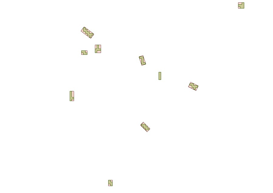
I would try rotating (Rotator using the center point) the geometry to get the measures horizontal and vertical and the create a bounding box (BoundingBoxReplacer).
The box will get you the width and height.
the result would totally depend on the shape of the polygons.
Why choose center point? No reason to assume it would represent some "axis".
Maybe just densify the polygons. Extract vertices.
Unconditionally merge them. Create lines form those.
Find (or keep) line(s) which are closest to required orientation. (using for instance the azimuth calculator)
Extract length and statistically calculate the min and max.
(you could make an iterative process to continue until the min max does not change significantly.)
I would try rotating (Rotator using the center point) the geometry to get the measures horizontal and vertical and the create a bounding box (BoundingBoxReplacer).
The box will get you the width and height.
I created an example template for this case, using FME 2018:
test.fmwt
I played around yesterday and found that an orientated bounding box which I then can align to a desired heading, chop up and then measure the lines would give me the desired length and width which suffices in a quick manner.

I played around yesterday and found that an orientated bounding box which I then can align to a desired heading, chop up and then measure the lines would give me the desired length and width which suffices in a quick manner.

Good catch. If your goal is to get short/long side lengths of the oriented bounding box, you can just specify attribute names to the Length of Shorter/Longer Attribute parameters in the BoundingBoxReplacer.