I cannot understand what the goal is, unfortunately. Could you please illustrate the source polygons (layer 1) and corresponding result (layer 2) using some images?
For each area in layer 1 i have to create a " fictional installation", which is a small polygon.
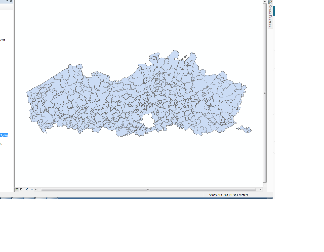
I thought that the method above was the easiest way to do that. The printscreen below is layer one.
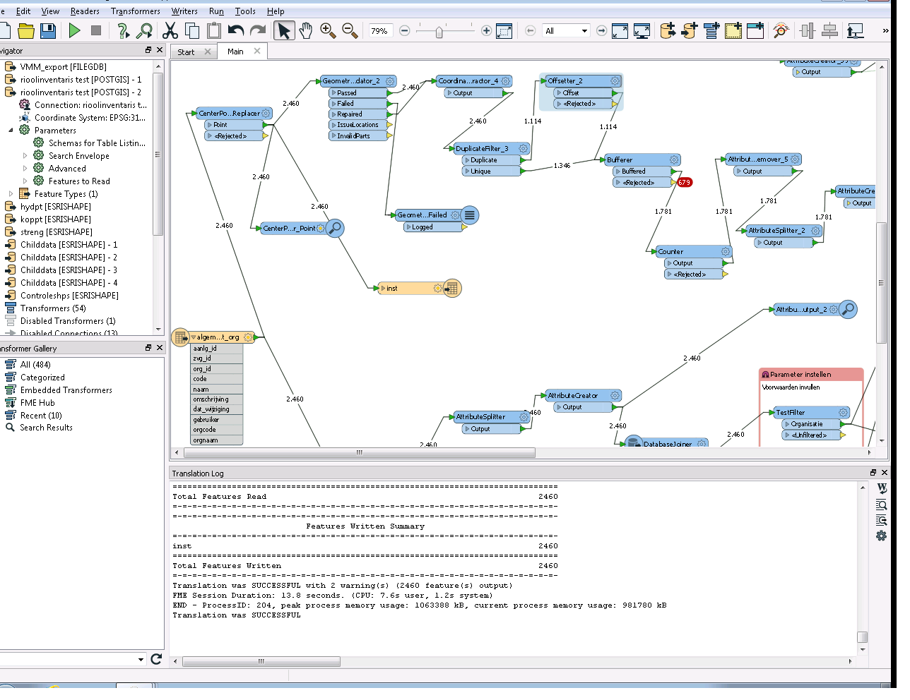
This is the FME model i tried but the buffer rejects and i don't know why.
I have an automation setup in FME Server 2021.1 that polls an inbox and parses the pdf email attachment. I'm receiving a failure from the reader attempting to parse the pdf with a filename that contains a certain character –. It is reading the character as "??". I tried to identify this online and it shows it as U+2013 : EN DASH. I can see this is a formatting issue, but what can I do to fix this if I have no control over the filename that will be sent to the inbox?
Filename
Invoice #2071 - 5559 REDACTED TR D #1256 – Proration.pdf
FME Server Error
2021-7-22 09:20:33 | PDF2D reader: PDF Reader: Failed to open document 'C:\ProgramData\Safe Software\FME Server\resources\system\temp\emailattachments\20210720120551-REDACTED_Invoicing-REDACTED_-_Fixed_Bid-8d4ca970-18b5-4f8b-84b3-c10893d5e69e\Invoice #2071 - 5559 REDACTED TR D #1256 ?? Proration.pdf' because it does not exist or because the reader does not have permission to access the file
Are you using a fixed value for the buffer amount or a value derived from an attribute?
a fixed value because it doesn't really matter, i just have to have something for each polygon of layer 1 (The only condition is that in layer 2 the polygons do not overlap, so I use the offsetter).
This is the FME model i tried but the buffer rejects and i don't know why.
It's difficult to know what happened only from the screenshot. Connect an Inspector to the Rejected port and see what the "fme_rejection_code" says.
a fixed value because it doesn't really matter, i just have to have something for each polygon of layer 1 (The only condition is that in layer 2 the polygons do not overlap, so I use the offsetter).
If you attach an inspector to the rejected buffer output what does it say in fme_rejection_code?
It's difficult to know what happened only from the screenshot. Connect an Inspector to the Rejected port and see what the "fme_rejection_code" says.
It says "invalid geometry type"
It's difficult to know what happened only from the screenshot. Connect an Inspector to the Rejected port and see what the "fme_rejection_code" says.
Make sure that all the input features were valid areas and also the CenterPointReplacer created points correctly for all the input features.
For each area in layer 1 i have to create a " fictional installation", which is a small polygon.
I thought that the method above was the easiest way to do that. The printscreen below is layer one.
@nath, do you want to create the Fictional Installations based on where the polygons overlap? What is your criteria for determining where the fictional instalations should go?
Hi @nath
could you please examine features rejected by Bufferer? What are they? What is their geometry type? If you could post a data Inspector screenshot with one of the rejected features format attributes, it would be very helpful.
What FME version do you use? Is it FME 2017 or older? If it is an older version, could you please share your build number?
My immediate suspicion is aggregate features. If you have an aggregate of a polygon and a null geometry feature, then the feature is deaggregated. The polygon gets buffered but the null geometry gets rejected. Maybe put an AggregateFilter before the Bufferer transformer, or a Deaggregator and then a GeometryFilter to get rid of features that can't be buffered.
@nath, do you want to create the Fictional Installations based on where the polygons overlap? What is your criteria for determining where the fictional instalations should go?
The only criteria is that the new polygon is somewhere inside the old polygon. It doesn't matter where.
@nath
AreaOnArea, test for overlaps =0
create center points of resulting objects.
Extract coordinates of resulting obejcst.
Merge with center point (featuremerger 1=1)
Calculate distance = root(x squared plus y squared)
Statistics calculator to get minimum.
2DArcReplacer with center point and x axis =yaxis = minimum.
Gives non overlapping circles within the polygons.
(maybe some shoehorn type polygons will though..)
It is also possible to scale the original polygon inside the resulting circles. Bit more calculation. (maybe if I got some time left ill post it soon..)