Solved

Is there a way to control the size of labels within AutoCAD blocks during DWG rendering?

  • January 14, 2020
  • 8 replies
  • 108 views

kweller
Contributor
Forum|alt.badge.img+8

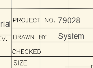
Is there a way to control the size of labels within AutoCAD blocks during DWG rendering? The text looks smaller and is misaligned when rendered by FME (and therefore the inspector and, more importantly, the PNG writer), but it's the right size and aligned properly in AutoCAD.

Bad in FME (for Linux):

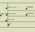
vs. Good in AutoCAD:


Best answer by kweller

Thanks @daveatsafe! I already use a Text Stroker feeding a MapnikRasterizer to produce my PNGs. The problem was more of a mis-alignment issue than a size issue. I just solved the problem by inserting an Offsetter to fix the former, and also by multiplying the font size by a factor of 1.4 to get the TextStroker and MapnikRasterizer to output something resembling what AutoCAD renders for the same content.

So I've solved the problem on my own. I just think It's odd that the default FME text positioning--not just the text size--is off.

View original
Did this help you find an answer to your question?

8 replies

daveatsafe
Safer
Forum|alt.badge.img+19
  • Safer
  • January 16, 2020

Hi @kweller,

FME's default rasterization when writing to PNG is pretty basic when it comes to text. You can get better results if you use the TextStroker transformer before writing, which allows you to choose the font for the text to render.

For the best rasterization results, please look at the MapnikRasterizer, which allows you to fully control the appearance of your lines, polygons and text in the output raster. The setup can be a little complex, but the results are definitely worth it. For more information on the MapnikRasterizer capabilities, please see:

https://knowledge.safe.com/articles/1092/introduction-to-mapnikrasterizer.html


kweller
Contributor
Forum|alt.badge.img+8
  • Author
  • Contributor
  • Best Answer
  • January 16, 2020

Thanks @daveatsafe! I already use a Text Stroker feeding a MapnikRasterizer to produce my PNGs. The problem was more of a mis-alignment issue than a size issue. I just solved the problem by inserting an Offsetter to fix the former, and also by multiplying the font size by a factor of 1.4 to get the TextStroker and MapnikRasterizer to output something resembling what AutoCAD renders for the same content.

So I've solved the problem on my own. I just think It's odd that the default FME text positioning--not just the text size--is off.


daveatsafe
Safer
Forum|alt.badge.img+19
  • Safer
  • January 16, 2020
kweller wrote:

Thanks @daveatsafe! I already use a Text Stroker feeding a MapnikRasterizer to produce my PNGs. The problem was more of a mis-alignment issue than a size issue. I just solved the problem by inserting an Offsetter to fix the former, and also by multiplying the font size by a factor of 1.4 to get the TextStroker and MapnikRasterizer to output something resembling what AutoCAD renders for the same content.

So I've solved the problem on my own. I just think It's odd that the default FME text positioning--not just the text size--is off.

Hi @kweller,

There are a couple of AutoCAD quirks that may be responsible:

- AutoCAD stores the lower left location of the text, regardless of the justification set on the text, then recalculates the apparent placement point based on the font metrics. FME attempts to repeat the calculation to set the placement location as the attributes autocad_alignment_x, _y and _z. However, FME does not have access to the font metrics, and so this location is only approximate.

- AutoCAD's text size is based on the capital height of the font, while most other formats (and FME's rendering) use ascender plus descender. This results in the text shrinking to about .7 when converting to other formats. Unfortunately, DWG is one of FME's original 9 formats, and so we can't change this behavior without breaking 25 years of backwards compatibility.


kweller
Contributor
Forum|alt.badge.img+8
  • Author
  • Contributor
  • January 16, 2020
daveatsafe wrote:

Hi @kweller,

There are a couple of AutoCAD quirks that may be responsible:

- AutoCAD stores the lower left location of the text, regardless of the justification set on the text, then recalculates the apparent placement point based on the font metrics. FME attempts to repeat the calculation to set the placement location as the attributes autocad_alignment_x, _y and _z. However, FME does not have access to the font metrics, and so this location is only approximate.

- AutoCAD's text size is based on the capital height of the font, while most other formats (and FME's rendering) use ascender plus descender. This results in the text shrinking to about .7 when converting to other formats. Unfortunately, DWG is one of FME's original 9 formats, and so we can't change this behavior without breaking 25 years of backwards compatibility.

Yeah, I figured it was something like that. 25 years is a long time in terms of technology.


deanhowell
Influencer
Forum|alt.badge.img+23
  • Influencer
  • January 16, 2020
kweller wrote:

Thanks @daveatsafe! I already use a Text Stroker feeding a MapnikRasterizer to produce my PNGs. The problem was more of a mis-alignment issue than a size issue. I just solved the problem by inserting an Offsetter to fix the former, and also by multiplying the font size by a factor of 1.4 to get the TextStroker and MapnikRasterizer to output something resembling what AutoCAD renders for the same content.

So I've solved the problem on my own. I just think It's odd that the default FME text positioning--not just the text size--is off.

Hello @kweller, any chance you can share a snapshot of your solution (or the workbench :)) as I am trying to do a similar thing in trying to recreate the DWG output.


kweller
Contributor
Forum|alt.badge.img+8
  • Author
  • Contributor
  • January 17, 2020
deanhowell wrote:

Hello @kweller, any chance you can share a snapshot of your solution (or the workbench :)) as I am trying to do a similar thing in trying to recreate the DWG output.

Sure! Here are a couple of screenshots. One is of the [Text]Offsetter and TextStroker that feed the MapnikRasterizer Text input port, and the other is the ExpressionEvaluator that updates the text font size (I went with 1.2x in the end).


deanhowell
Influencer
Forum|alt.badge.img+23
  • Influencer
  • January 19, 2020
kweller wrote:

Sure! Here are a couple of screenshots. One is of the [Text]Offsetter and TextStroker that feed the MapnikRasterizer Text input port, and the other is the ExpressionEvaluator that updates the text font size (I went with 1.2x in the end).

Thanks @kweller, what parameters did you us in the offsetter?


kweller
Contributor
Forum|alt.badge.img+8
  • Author
  • Contributor
  • January 20, 2020
deanhowell wrote:

Thanks @kweller, what parameters did you us in the offsetter?

X +0.05 and Y -0.02. But that's dependent on the spatial reference system and the font I'm using, so your numbers will likely need to be different. I'd suggest you experiment until you get the image output you want.


Cookie policy

We use cookies to enhance and personalize your experience. If you accept you agree to our full cookie policy. Learn more about our cookies.

 
Cookie settings