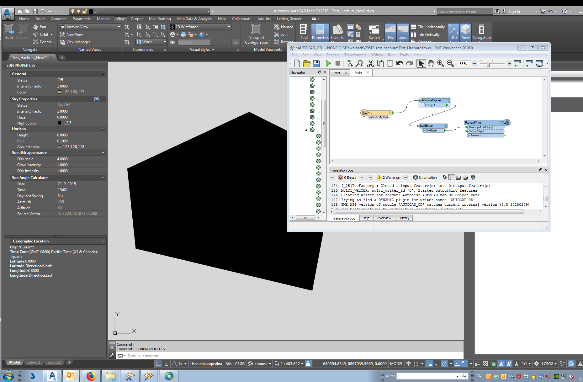
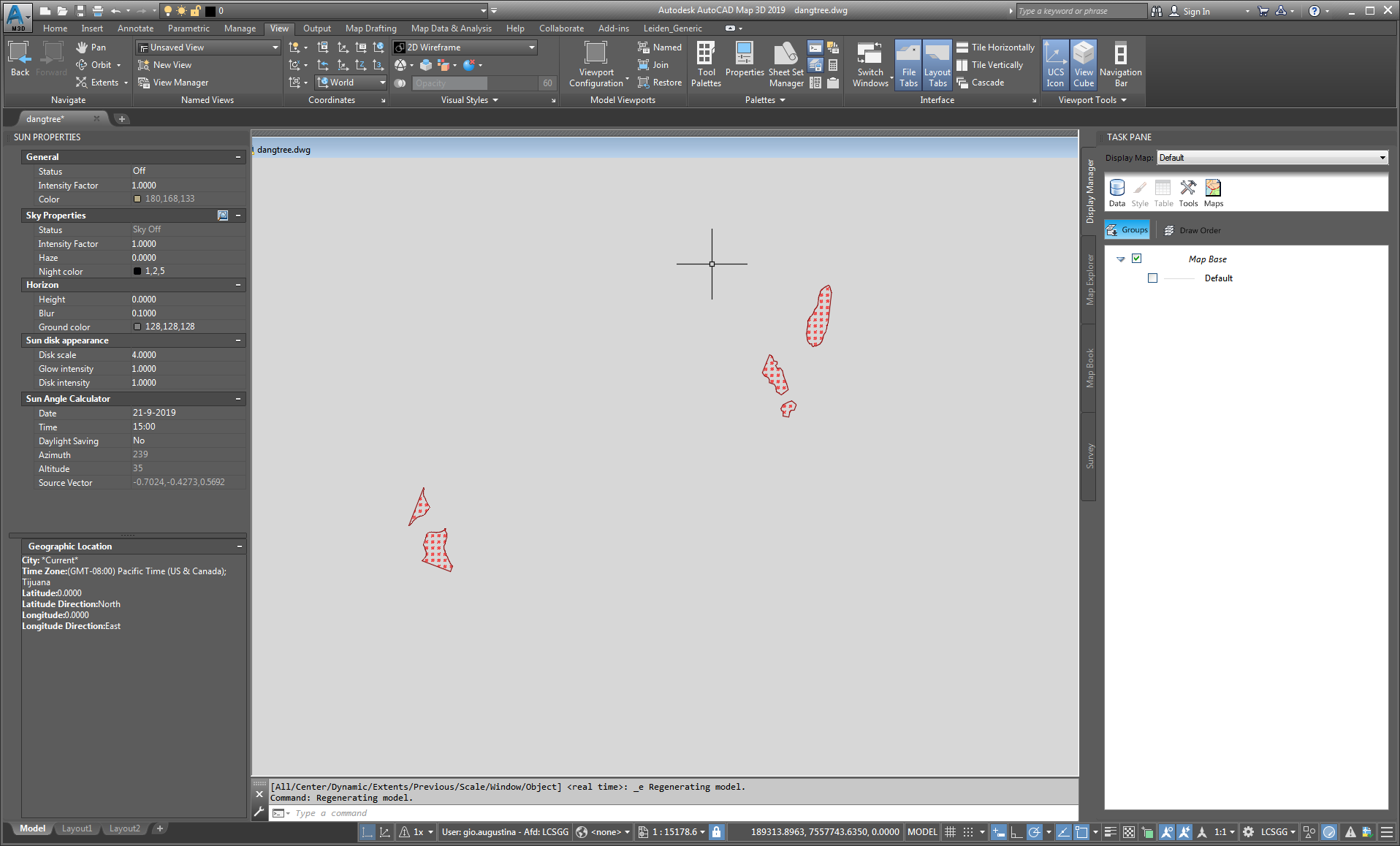
I'm doing a CAD to CAD conversion, but my final file, is constantly losing the hatches, in most cases do not show the hatches in the output file. Could someone help me and tell you what's going on? Follow my template
Thank´s
This post is closed to further activity.
It may be an old question, an answered question, an implemented idea, or a notification-only post.
Please check post dates before relying on any information in a question or answer.
For follow-up or related questions, please post a new question or idea.
If there is a genuine update to be made, please contact us and request that the post is reopened.
The hatch patterns from the source file may not be defined in your Template.dwg file. Please try using your source DWG file as the template file for the RealDWG writer instead - only the definitions will be copied, not the data.
Hi @DaveAtSafe
I finished my tests. Using the input file as a template, but the result was the same ... without hatches.
The hatch patterns from the source file may not be defined in your Template.dwg file. Please try using your source DWG file as the template file for the RealDWG writer instead - only the definitions will be copied, not the data.
Hi @DaveAtSafe,
I have already tried that and the result is still not OK after checking the result in a DWG Viewer. I wonder if it has to do with the lack of AutoCAD patterns that are not available with the FME installation.
The hatch patterns from the source file may not be defined in your Template.dwg file. Please try using your source DWG file as the template file for the RealDWG writer instead - only the definitions will be copied, not the data.
Attached is a template reading a singel (problematic) feature type, filtering on format attributes and using the those values in a DWGStyler.
The source file is used as a template in the writer and DWGStyler transformer.
The warning in the log shows the following:
AutoCAD Writer: The combination of pattern type 'Pre-defined' and pattern name 'GOST_GLASS' was found to be invalid. Using a default predefined hatch pattern of value of 'SOLID'
what is the pattern type 'Pre-defined' ?
Created using FME 2018.1.1.1 (20181203 - Build 18578)
Seems limited to (at least) the GHOST_GLASS pattern. (maybe some others, but did not check myself)
I tried different patterns and they all appear in AutoCAD...but GHOST_GLASS refuses.
According to some autocad forums the problem would be the driver of the graphic card(?!)
I have not checked that, but I seem not able to apply it (ghost_glass) using fme
Earlier post on this forum concerning the same problem (Did you search the forum?) indicate fme not performing well with associative hatches. (like Donald says: I dunno, maybe it is, maybe not!)
My problem is with Solid hatches. I did a lot of research and this is the only post identical to my problem. Attached Test_Hachure.zip is the input AutoCad file, the FME script, and the DWG output.
I tried all types of Writer. My hatch is not associative and besides, it has no outline. The only difference found is the absence of the surface value in the properties of the entity in AutoCad.
In fact, "Test_Hachure.dwg" is the input file of the FME script and "Test_Hachure_New.dwg" is the result.
It is in this last file that the problem arises and the variable "Fillmode" is at 1. It can be found with a "ctrl + A", we can see that it has no surface property.
If we move a vertex of the object, at that moment, the hatch appears!
Bye
Chris
@chriscool
I see the problem (more or less).
If you change the reader settings on "Test_Hachure.dwg" you get 2 objects.
In your reader it is 1. Seems like just hatchdefinition is passed, its border definition.
Don't know how t.b.h.
But, i found that if you just stick a dwg styler between the exposer and the feature writer, slect the pattern you want, it works fine.
Setting the pattern attribute manualy (atributecreator) did not succeed, using dwg styler did work...
I recently had the same problem, but only when the hatches already exist from an input drawing. I found out that FME reads the autocad_hatch_style attribute as a number while a DWG writer expects a name (i.e. "acid").
So, the workaround is to expose the attribute autocad_hatch_style and overwrite it with the correct style name or (in my case even better): simply remove the attibute!
Call for Safe: please resolve this tiny but annoying bug;)