Hi @moustik,
According to the RasterConvolver docs, specifying a weight of 0 signifies the cell will not participate in the calculation. This makes it possible to specify custom shapes of the kernel.
In the Advanced Properties of the RasterConvolver, please try setting Center Pixel to Ignore Pixel Nodata and Neighbor Pixel Handling to Use Center Pixel.
Hi @daveatsafe ,
I have used both of those parameters already, which is why I am asking.
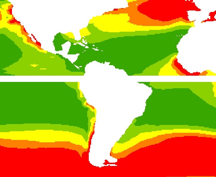
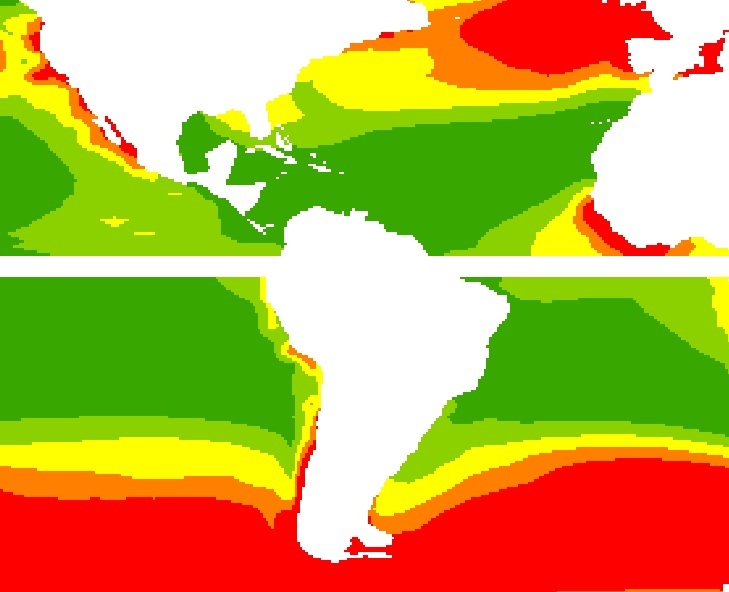
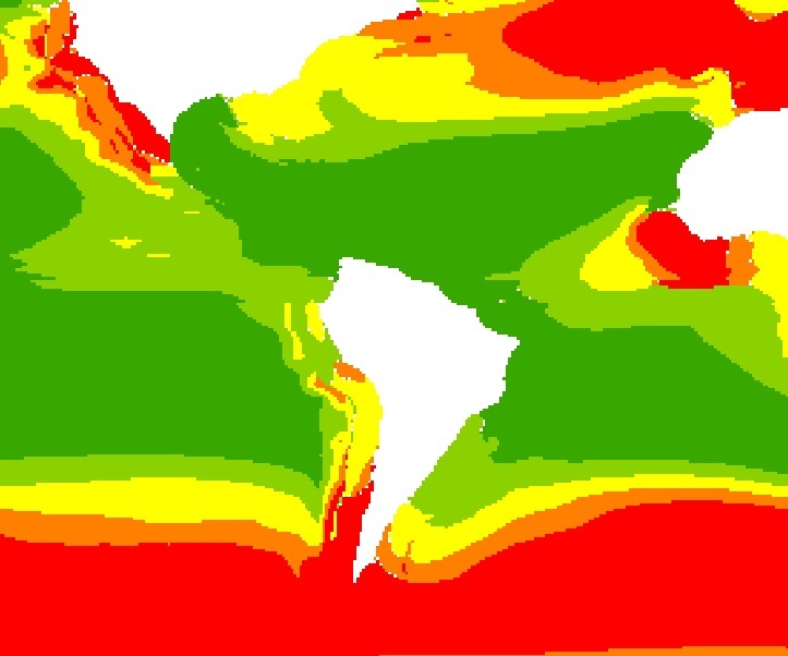
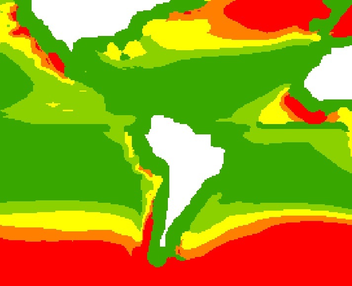
The aim of the matrices is to calculate cells to fill nodata value from initial map/figure that are 10 cell-radius away of the coast.
I will put different figures below to tell you what I am looking for:
Figure A is the starting point, giving figure B in Arc using a radial matrix with a radius of 10 cells
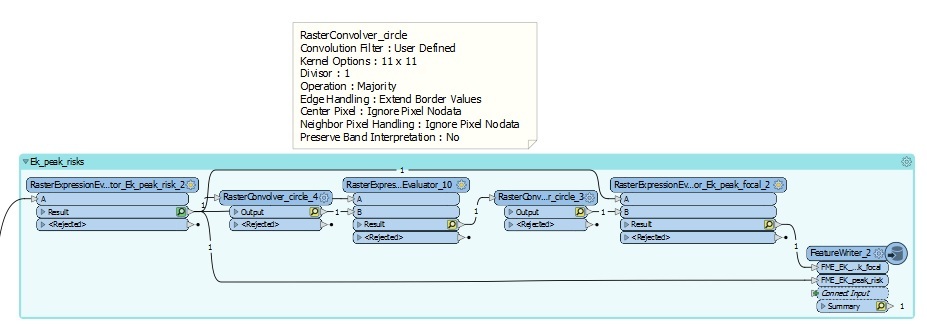
FME_Figure_A (which is the same as Figure_A), Figure C is supposed to give the same results as figure B (which is not), using 2 raster convolver with radial matrices (0 in corners) with a radius of 5 cells. The calculated values that are kept are the ones where there is nodata in Figure A (or FME_Figure_A).
Figure A
FME_Figure AFigure B
Figure C
Here is the transformers suite I used:
Hi @moustik,
According to the RasterConvolver docs, specifying a weight of 0 signifies the cell will not participate in the calculation. This makes it possible to specify custom shapes of the kernel.
In the Advanced Properties of the RasterConvolver, please try setting Center Pixel to Ignore Pixel Nodata and Neighbor Pixel Handling to Use Center Pixel.
Hello @daveatsafe ,
Have you seen my answer below ?
Thanks
Hi @daveatsafe ,
I have used both of those parameters already, which is why I am asking.
The aim of the matrices is to calculate cells to fill nodata value from initial map/figure that are 10 cell-radius away of the coast.
I will put different figures below to tell you what I am looking for:
Figure A is the starting point, giving figure B in Arc using a radial matrix with a radius of 10 cells
FME_Figure_A (which is the same as Figure_A), Figure C is supposed to give the same results as figure B (which is not), using 2 raster convolver with radial matrices (0 in corners) with a radius of 5 cells. The calculated values that are kept are the ones where there is nodata in Figure A (or FME_Figure_A).
Figure A
FME_Figure AFigure B
Figure C
Here is the transformers suite I used:
Hi @moustik,
Would you mind sharing a copy of your workspace?
Hi @moustik,
Would you mind sharing a copy of your workspace?
Hello @daveatsafe ,
You'll find a copy attached here.
Thanks
Hi @moustik,
Would you mind sharing a copy of your workspace?
Hi @moustik,
Thank you for the workspace, but it is a little too complex for diagnosing this issue. Would you mind simplifying to just a single RasterConvolver, and including a test dataset and the process you are trying to replicate in ArcGIS?
Hi @moustik,
Would you mind sharing a copy of your workspace?
Hello @daveatsafe ,
I want to replicate the ArcGIS output in FME.
The inputs are Ek_peak_risk1 and Ek_time_risk1 TIF files.
ArcGIS, using a FocalStat tool, extends the value of the raster cells where there is no value yet.
In Arc, the tool uses a circle of radius 10 cells where it applies a Majority operation. For this reason, I am using 2 raster Convolver with circle (putting weight 0 for the corner of the matrix) with a 5 cell radius (matrix 11 x 11).
I zipped the folder containing the different outputs (the ones from Arc and the ones from the FME tool)
Cheers
Hi @moustik,
Would you mind sharing a copy of your workspace?
Hi @moustik,
Maybe try using a 21x21 convolution instead of the two 11x11 convolutions. You can do this by setting the Size to Derived from Weights, then providing the weights in an attribute.
I am attaching a modified workspace illustrating how to do this, and also create the weights list from a circle diameter.