FINAL UPDATE

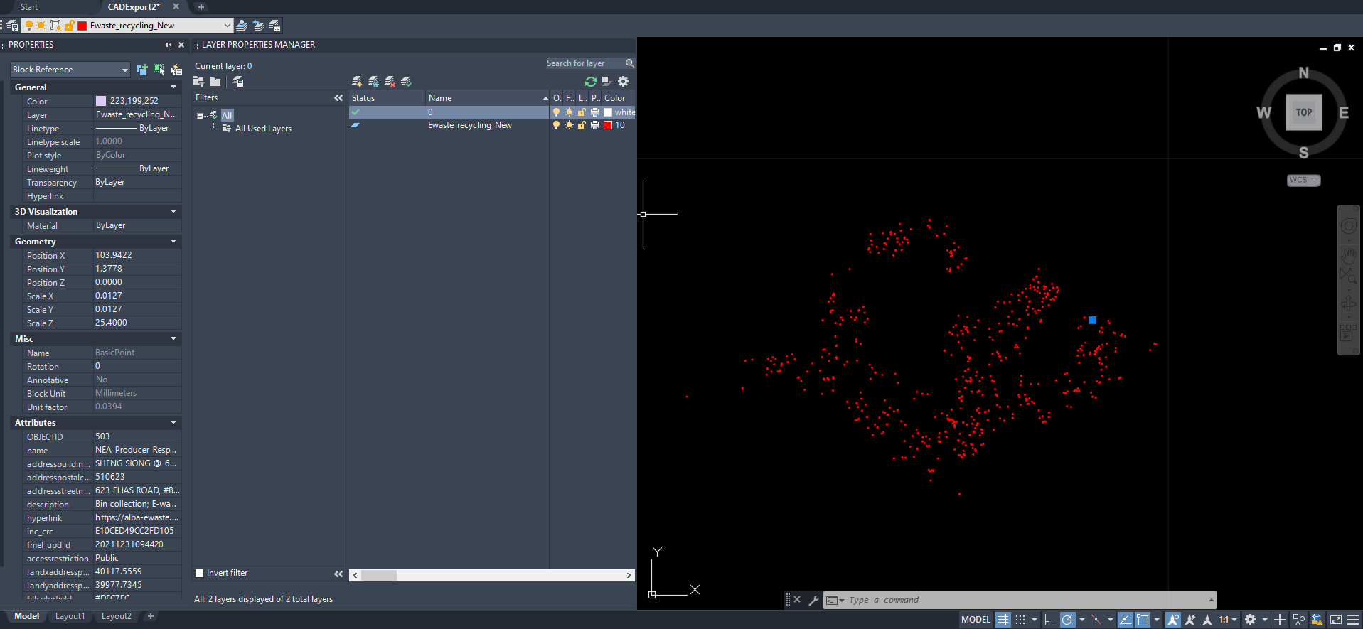
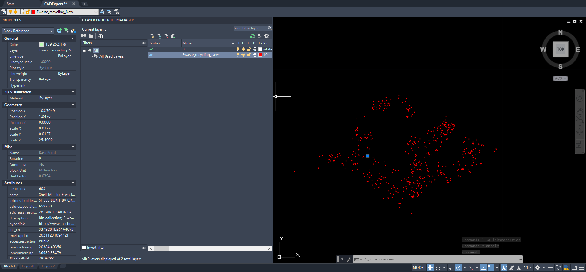
Turns out the problem was that the hatch fill in my block is incompatible with colors for some reason. Having a standalone circle for a block was ok. What I ended up doing was typing • via Text and then saving that as a block and now my CAD looks like a proper point layer.


2nd Update
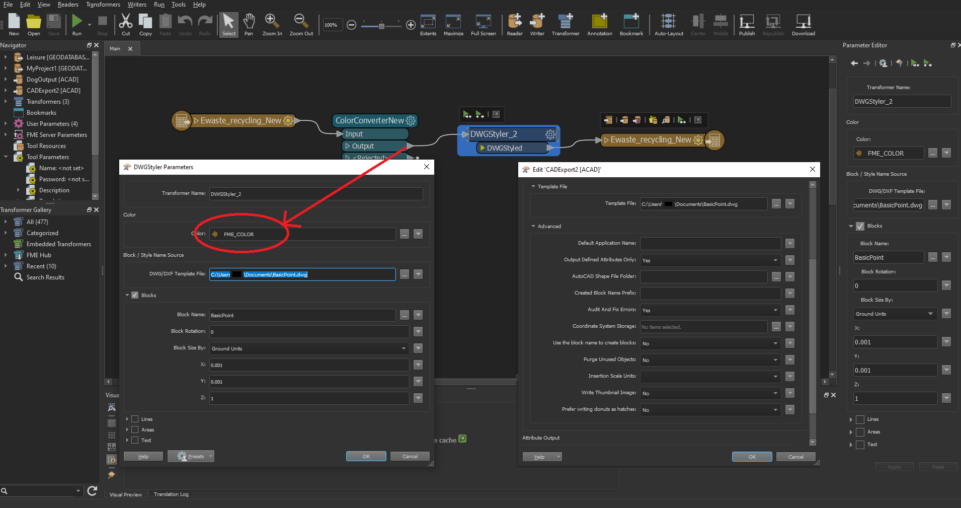
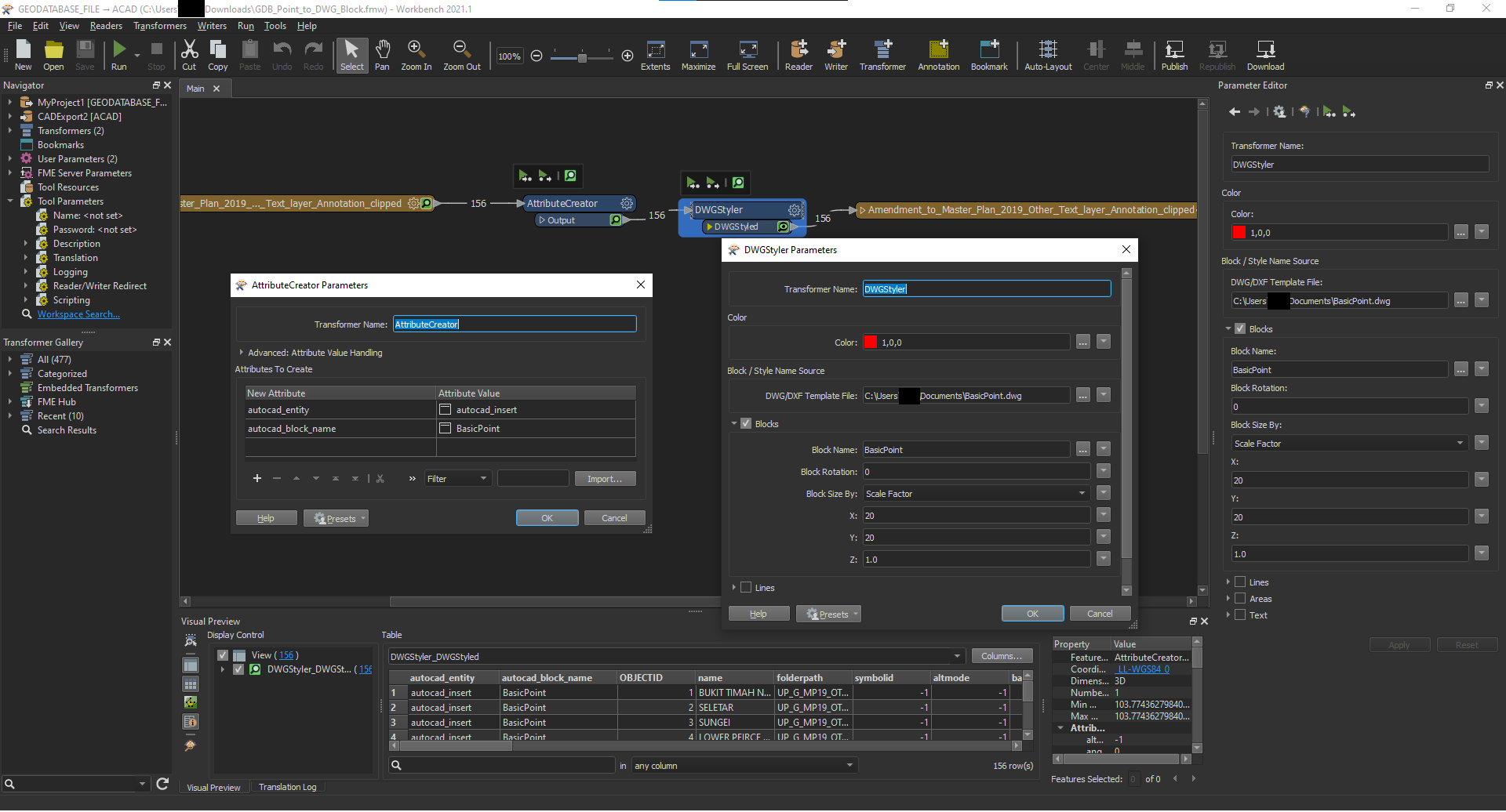
imageI added my template file to my writer parameters and I am now able to generate blocks for my individual points, but I can't seem to get the colors from my attributes to stick to my blocks.
imageUPDATE

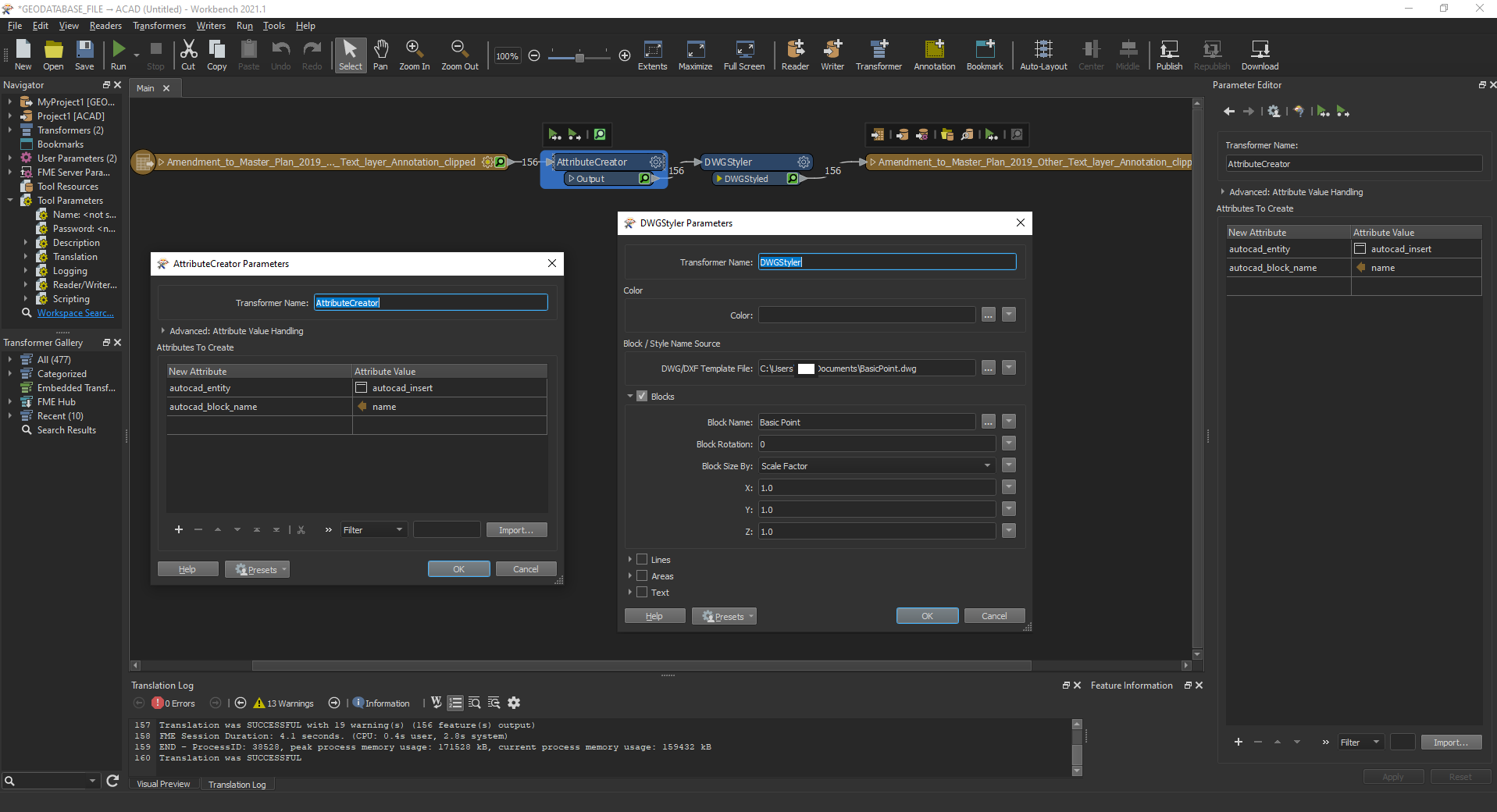
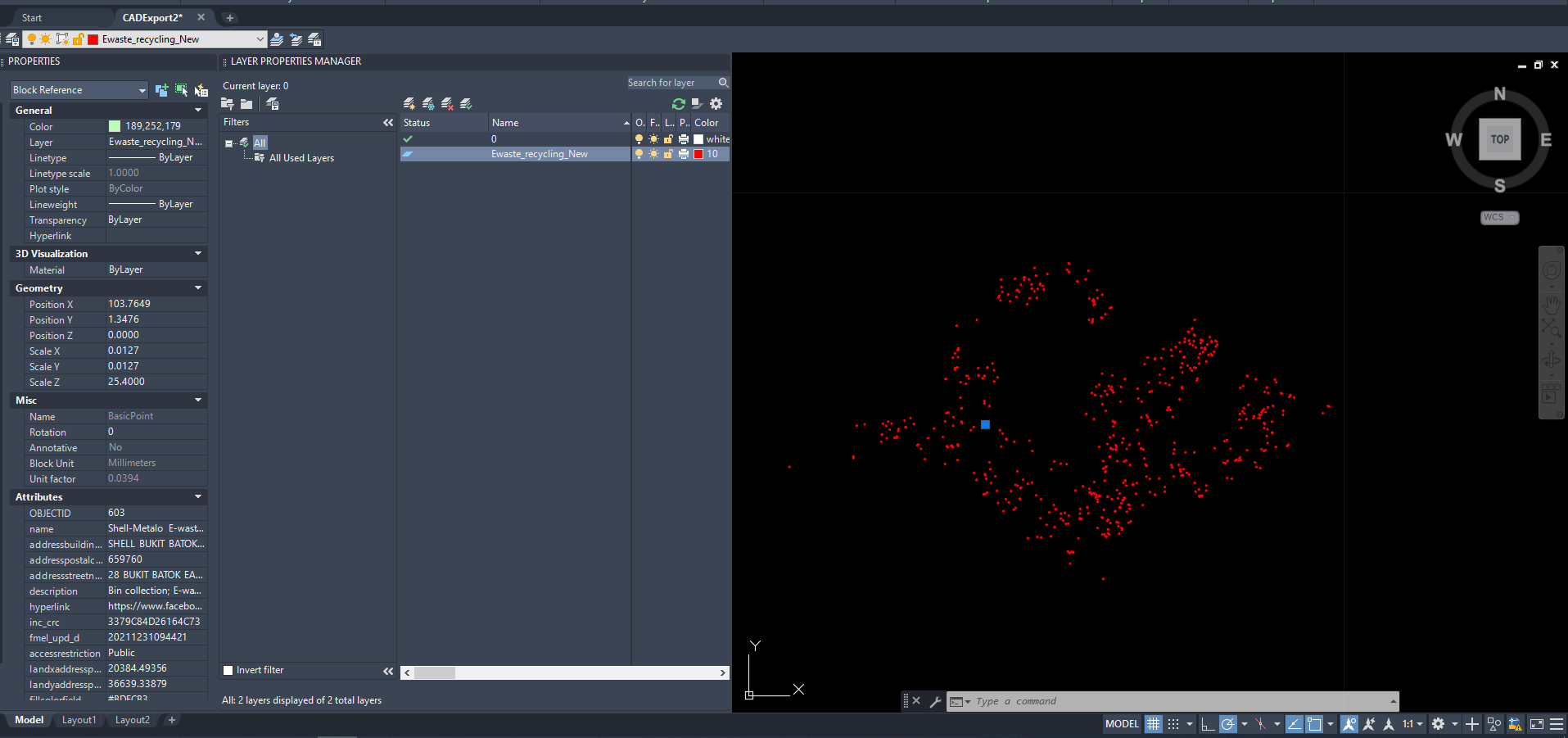
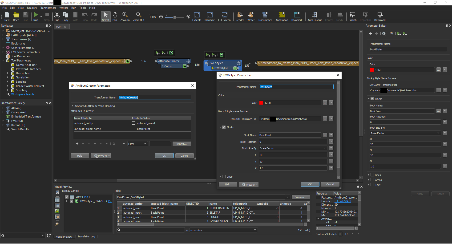
Updated Workflow, still not working 

This is my current workflow, but it still doesn't seem to produce a cad file with data inside all.


**Original Post below**

I have a point layer in an Esri GDB file I'm using workbench to convert to DWG AutoCAD data while maintaining color data. I have no issues with lines and polygonal layers but my understanding is that CAD uses blocks while Esri uses points.


I tried a direct conversion where I just had a reader with my GDB and a writer with my DWG and the end result was a file with the points as very tiny dots.


I'm currently trying to use a custom basic point created in AutoCAD as a Block template in the workflow. But what happens is that the layer after conversion is just empty, no more tiny dots of any sort at all. Trying to select anything gets me nothing in return.
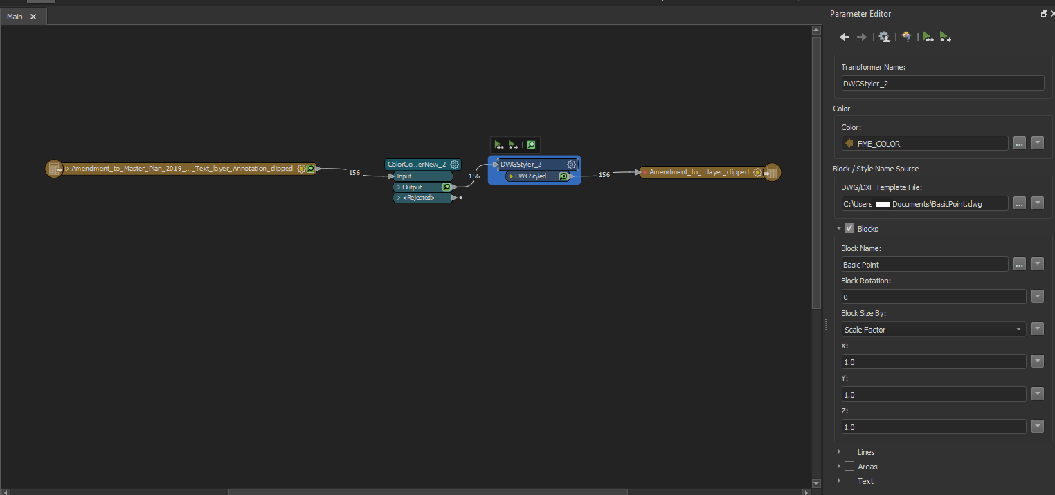
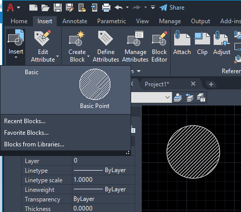
 

WorkspaceBasic Point block

Set the attributes

autocad_entity = autocad_insert

autocad_block_name = your name of the block


Set the attributes

autocad_entity = autocad_insert

autocad_block_name = your name of the block

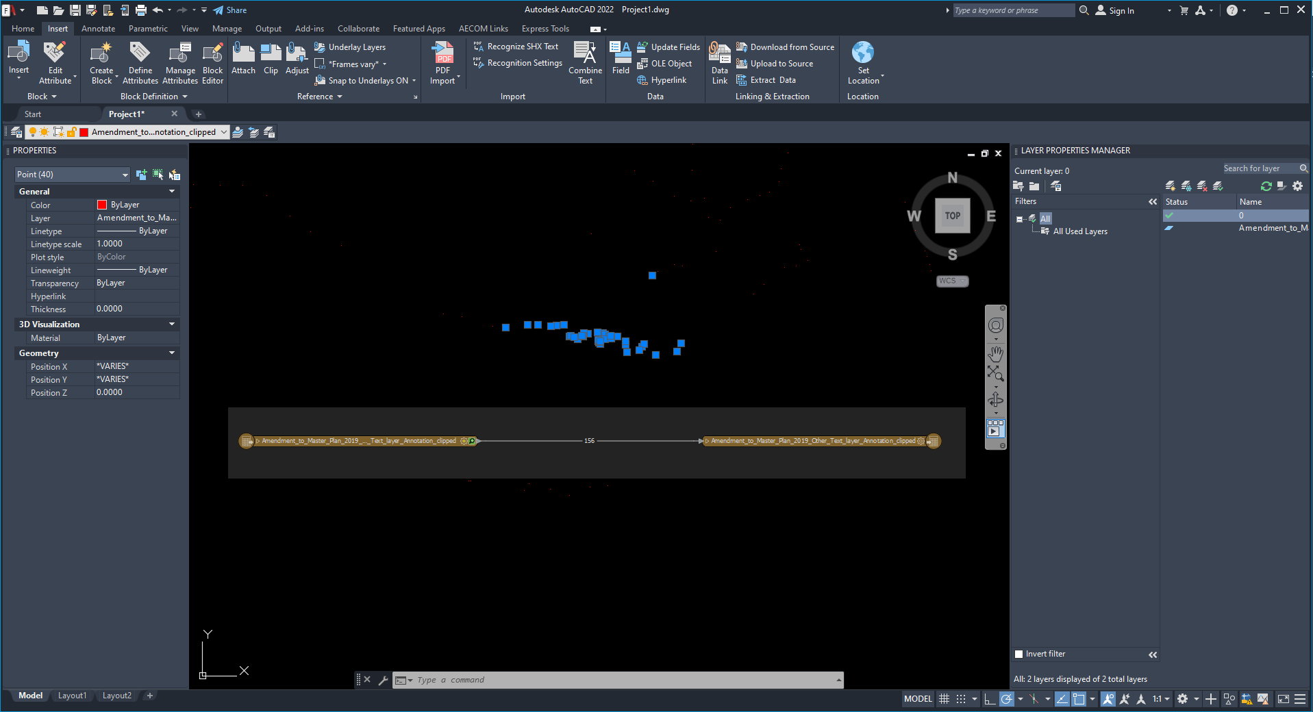
imageI don't think I'm doing this right, my output still produces an empty CAD file.

My solution is old school without DwgStyler.

Your block Name is "Basic Point"?


My solution is old school without DwgStyler.

Your block Name is "Basic Point"?

Yeap custom circle with a hatch fill in a separate DWG file.

What does your solution look like?

Are you using the AttributeCreator?


My solution is old school without DwgStyler.

Your block Name is "Basic Point"?

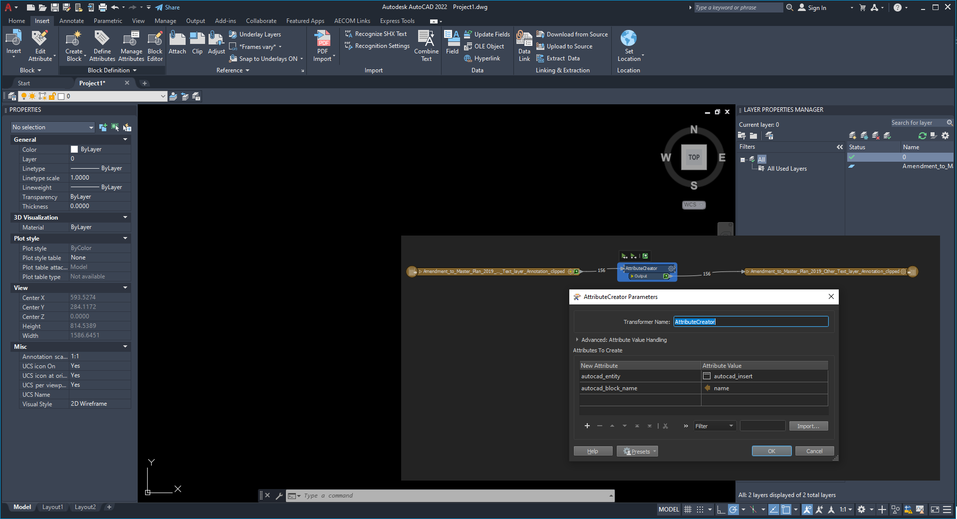
Direct conversion without any transformersimageUsing AttributeCreator, which seems to get rid of my points from my GDB (Sorry it didn't post earlier)
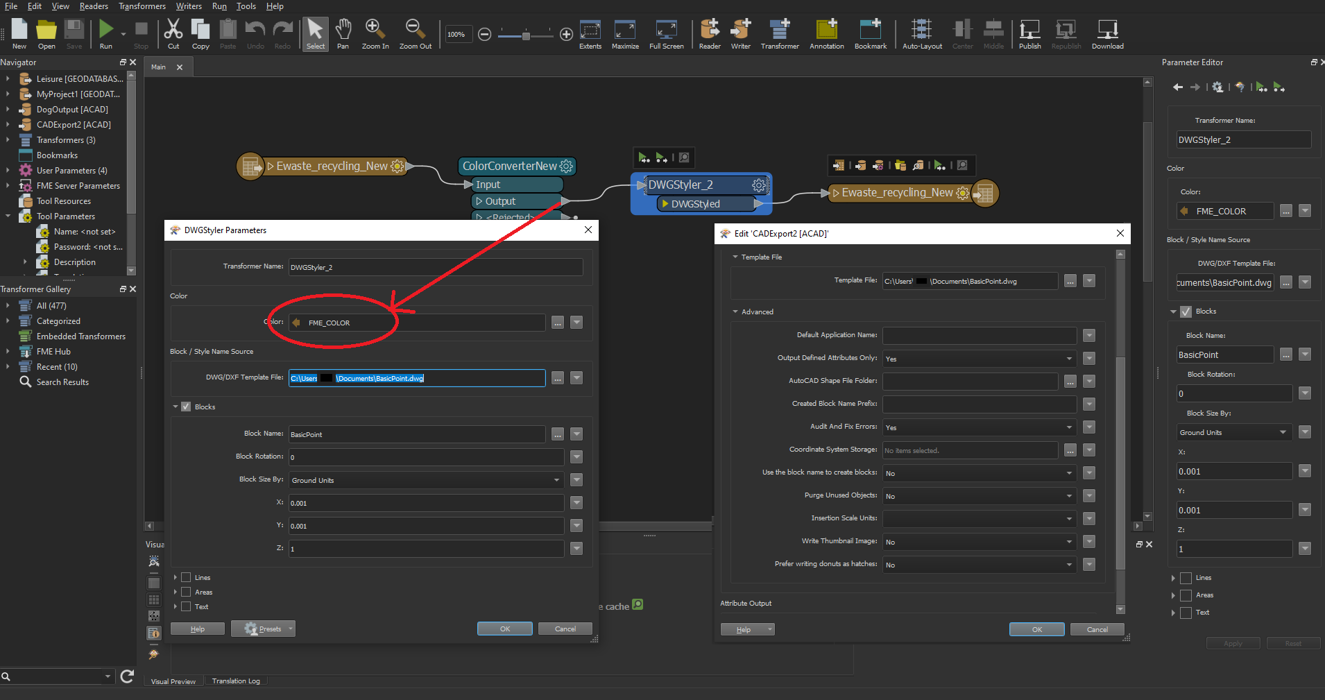
image


My solution is old school without DwgStyler.

Your block Name is "Basic Point"?

I realize I was using the wrong thing for my value for the autocad_block_name and I've updated it, but it still doesn't seem to work:


image


1) It's not necessary to use AttributeCreator AND DwgStyler. The DwgStyler set the attributes. Use the DwgStyler only.

2) If the destination does not show a block, then the template DWG-files has no block with the name.

Your template file with the name "BasicPoint.dwg" has a block inside named "BasicPoint"??

3) Help to DwgStyler: DWG/DXF Template File

This optional parameter is used to specify the name of an existing DWG, DXF, or DWT file that will be used by the transformer as a source for block names, linetypes, and text shape names. It is not used by the actual DWG/DXF writer – the template file must be specified in the writer’s parameters and should contain the same block names and linetypes as the file specified here. Usually the same file will be used in both the transformer and the writer.

If no blocks or linetypes will be used, this parameter can be left blank.


I'm using only the param Template File from the writer. This works.

Hi @tomfriedl​, I added my template file into my parameters for my writer and I'm able to get my points showing up as blocks in CAD now, thank you! Do you by any chance know how I can use FME workbench to color the blocks?


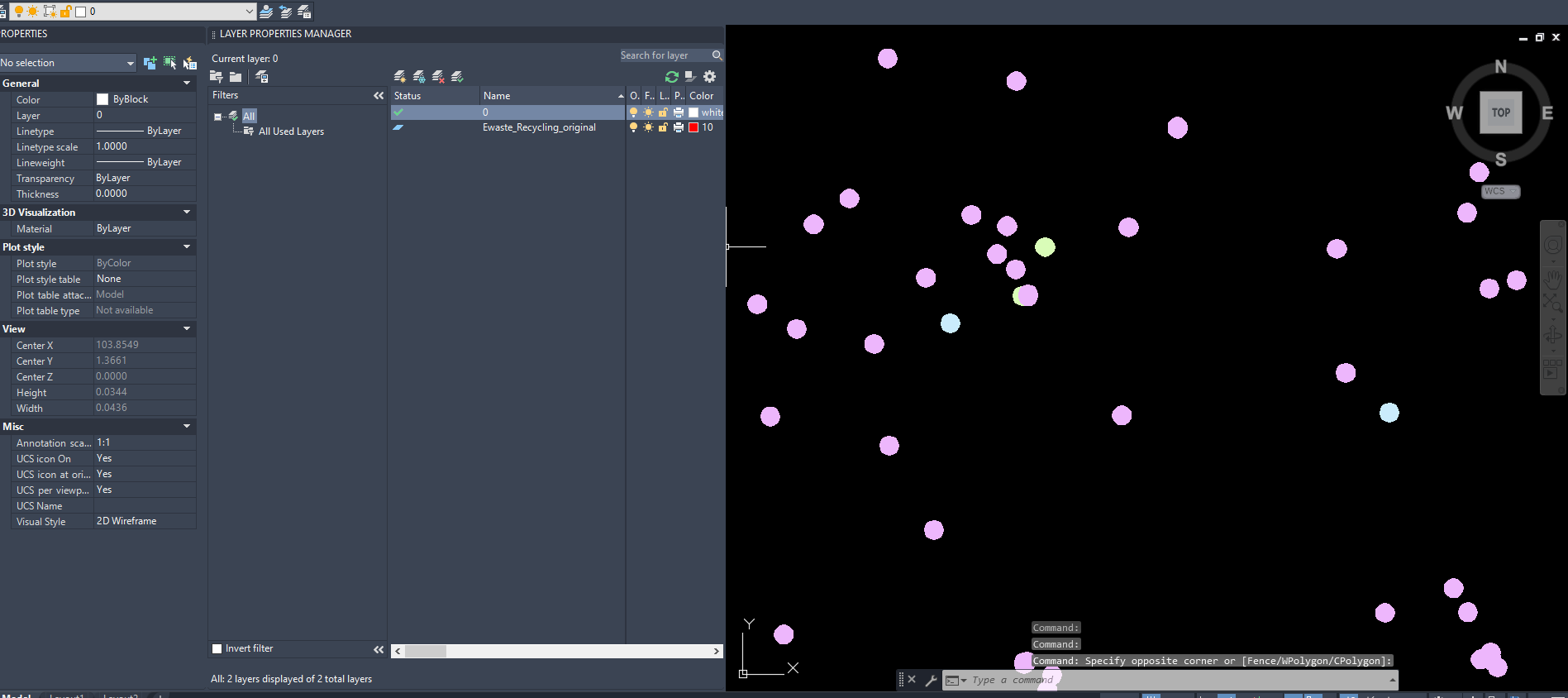
Color flowCAD colorOther point with other colorAs you can see the color data gets passed to the block but it references color from the layer for some reason?
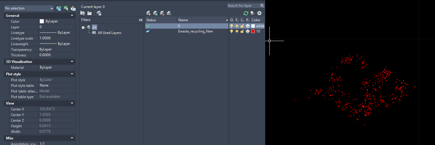

What's the definition of your color in AutoCad (Blockeditor)? I'think you must set the color to "ByBlock".


What's the definition of your color in AutoCad (Blockeditor)? I'think you must set the color to "ByBlock".

imageimageSelected all my points/blocks and switched to ByBlock and they're still red :/
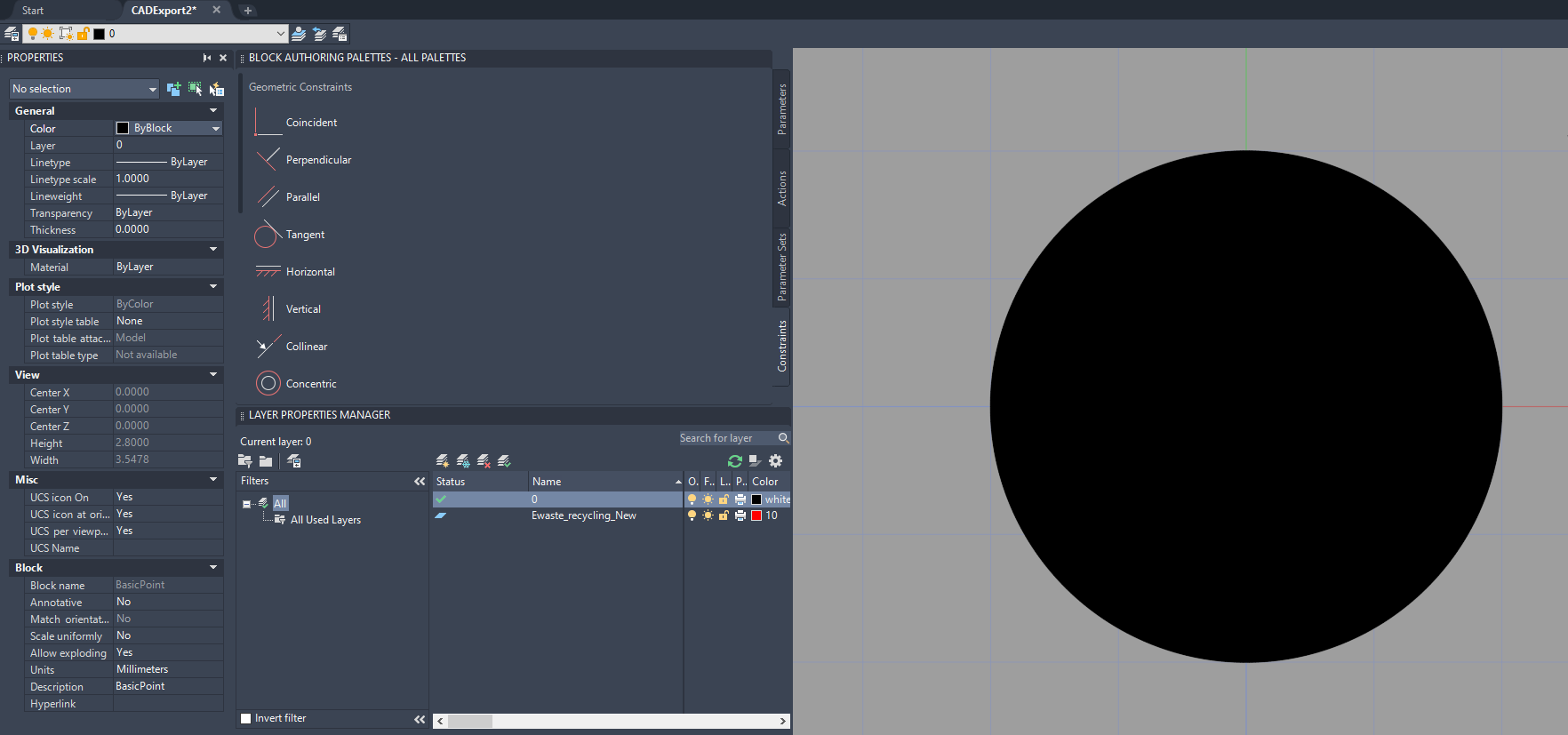
 

Made sure to update my block too but they still show up the same color even though I set it's color to be ByBlock and reran the entire workspaceimage


What's the definition of your color in AutoCad (Blockeditor)? I'think you must set the color to "ByBlock".

Hi @tomfriedl​ , just wanted to follow up, figured out that my block having a hatch fill inside of the circle prevents it from getting colors from DWG styler, so I ended up using a dot symbol in text as my template instead and I got results I wanted. A plain old circle and a text dot works.image 


Reply