Solved

DWG to raster (GeoTIFF)

  • January 26, 2018
  • 15 replies
  • 223 views

Forum|alt.badge.img

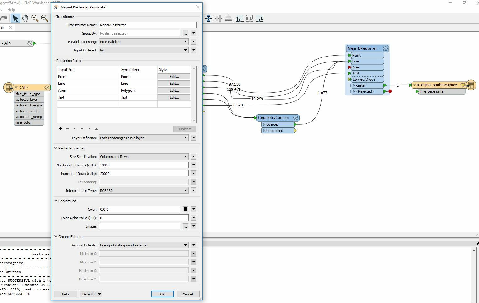
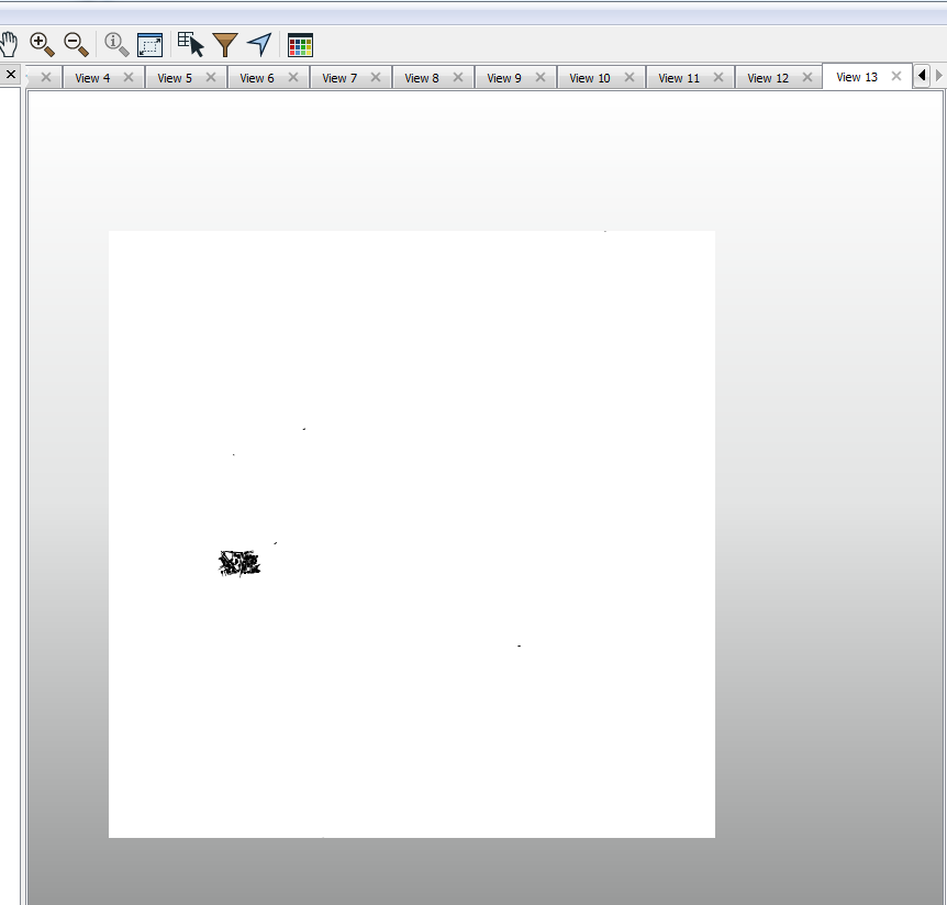
I am tryintg rasterize one dwg. I am using this scheme that can be seen on screenshot but unfortunately I am getting blank result. Does anybody have an idea what could be the problem?

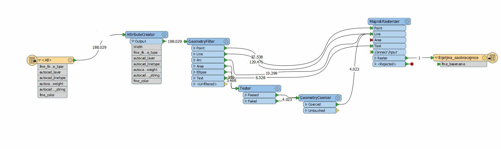
Best answer by pratap

Hi,

Could you please check the workbench attached.

Place one rectangle in AutoCAD by covering all the features

Pratap

14341-acad2geotiff.fmw

This post is closed to further activity.
It may be an old question, an answered question, an implemented idea, or a notification-only post.
Please check post dates before relying on any information in a question or answer.
For follow-up or related questions, please post a new question or idea.
If there is a genuine update to be made, please contact us and request that the post is reopened.

15 replies

jdh
Contributor
Forum|alt.badge.img+37
  • Contributor
  • 2002 replies
  • January 26, 2018

We would need to see the settings on your MapnikRasterizer. Though I am curious why you have a Tester with both ports going to the same GeometryCoercer.


Forum|alt.badge.img
  • Author
  • 63 replies
  • January 26, 2018

We would need to see the settings on your MapnikRasterizer. Though I am curious why you have a Tester with both ports going to the same GeometryCoercer.


Here it is. I forgot to disable and delete tester because I was trying to find a solution but it didn't work.


jdh
Contributor
Forum|alt.badge.img+37
  • Contributor
  • 2002 replies
  • January 26, 2018

Do you need an alpha channel?


Are you aware that the layers will be rendered in the order of the table? So potentially the points could be overwritten by the lines and polygons (not that there are any currently connected).


What style settings do you have on the Point?

Forum|alt.badge.img
  • Author
  • 63 replies
  • January 26, 2018

Do you need an alpha channel?


Are you aware that the layers will be rendered in the order of the table? So potentially the points could be overwritten by the lines and polygons (not that there are any currently connected).


What style settings do you have on the Point?
I would like alpha channel because I want my image to be transparent, so I can overlay it with some other images. My problem is that I get as a result empty image, no lines visible but when I click on img it gives me an informations about points and everything but I don't see anything.


Do You have an idea what could be the problem?


jdh
Contributor
Forum|alt.badge.img+37
  • Contributor
  • 2002 replies
  • January 26, 2018
I would like alpha channel because I want my image to be transparent, so I can overlay it with some other images. My problem is that I get as a result empty image, no lines visible but when I click on img it gives me an informations about points and everything but I don't see anything.


Do You have an idea what could be the problem?


Not from just the screen capture, sorry. Could you create a small sample of the source data, and upload the workspace here?


Forum|alt.badge.img
  • Author
  • 63 replies
  • January 26, 2018
Not from just the screen capture, sorry. Could you create a small sample of the source data, and upload the workspace here?


example-data.dwg


example-data.fmw


Here is small area example and also my workbench.


jdh
Contributor
Forum|alt.badge.img+37
  • Contributor
  • 2002 replies
  • January 26, 2018

So a lot of your fme_color attributes are set to 0,0,0 so they are being drawn as black, and indistinguishable from the background.


You also have a stray point in the upper right corner of your universe, which will cause the majority of the features to be less than 1 pixel in size when your ground extents are "use inputs"

Forum|alt.badge.img
  • Author
  • 63 replies
  • January 26, 2018

So a lot of your fme_color attributes are set to 0,0,0 so they are being drawn as black, and indistinguishable from the background.


You also have a stray point in the upper right corner of your universe, which will cause the majority of the features to be less than 1 pixel in size when your ground extents are "use inputs"
Well, I have made background black and I need only lines and points and text, I don't know why I don't get them as result? Do You have an idea how could I solve it?


jdh
Contributor
Forum|alt.badge.img+37
  • Contributor
  • 2002 replies
  • January 26, 2018
Well, I have made background black and I need only lines and points and text, I don't know why I don't get them as result? Do You have an idea how could I solve it?


Either specify explicitly the ground extents, or clip your data to get rid of the stray data


Use a background colour other than black, or change the feature fme_color to not be black.


Forum|alt.badge.img
  • Author
  • 63 replies
  • January 26, 2018
Either specify explicitly the ground extents, or clip your data to get rid of the stray data


Use a background colour other than black, or change the feature fme_color to not be black.


I have tried already to change to any other color, but nothing is changing, I keep getting the same result, I can't get everything in raster, just blank picture.


jdh
Contributor
Forum|alt.badge.img+37
  • Contributor
  • 2002 replies
  • January 26, 2018
I have tried already to change to any other color, but nothing is changing, I keep getting the same result, I can't get everything in raster, just blank picture.


Did you clip your data, or define your AOI? If not, then the stray data will cause the pixels to cover such a large ground area that your entire "real" data will be less than a single pixel.


gio
Contributor
Forum|alt.badge.img+15
  • Contributor
  • 2252 replies
  • January 26, 2018

@maliodpalube

dwg2mapnik.fmw

You have objects spread all over the place in the acad.

If you use groundextent it will create a extent with objects far apart.

I removed for instance D_TACKE_KOTE and then extracted bounds using BoundsExtractor after aggregating. Then deaggregate.

Used Specify ground extents to create the Raster.

Now u see the objects, but still somewhat small, because there are some remote (but less then with

D_TACKE_KOTE)

Best to clean you DWG first, or use tester to or bounding box to select the objects u want.


gio
Contributor
Forum|alt.badge.img+15
  • Contributor
  • 2252 replies
  • January 26, 2018

@maliodpalube

some pics

after removing far away objects..

after boundingobx..


Forum|alt.badge.img
  • Author
  • 63 replies
  • January 28, 2018

@maliodpalube

dwg2mapnik.fmw

You have objects spread all over the place in the acad.

If you use groundextent it will create a extent with objects far apart.

I removed for instance D_TACKE_KOTE and then extracted bounds using BoundsExtractor after aggregating. Then deaggregate.

Used Specify ground extents to create the Raster.

Now u see the objects, but still somewhat small, because there are some remote (but less then with

D_TACKE_KOTE)

Best to clean you DWG first, or use tester to or bounding box to select the objects u want.

Sorry but I couldn't download this workbench it gives me an error. Can You publish it again?

pratap
Contributor
Forum|alt.badge.img+12
  • Contributor
  • 605 replies
  • Best Answer
  • January 29, 2018

Hi,

Could you please check the workbench attached.

Place one rectangle in AutoCAD by covering all the features

Pratap

14341-acad2geotiff.fmw