
I'm trying to reproject a DWG file from AGD 1966 ISG 56 (EPSG:102077) to GDA2020 Zone 56 (EPSG:7856). I'm using the original DWG as a template to preserve layers, colours, line styles, etc.
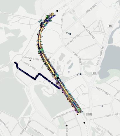
I've set up a workbench to handle the reprojection and all the data looks good and in the correct location when viewed at the final step in the inspector:
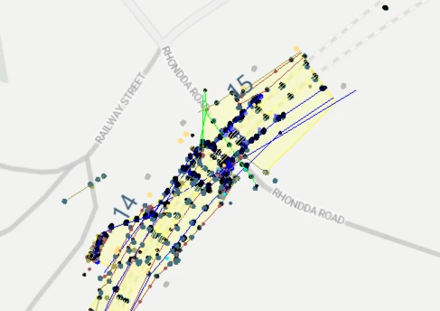
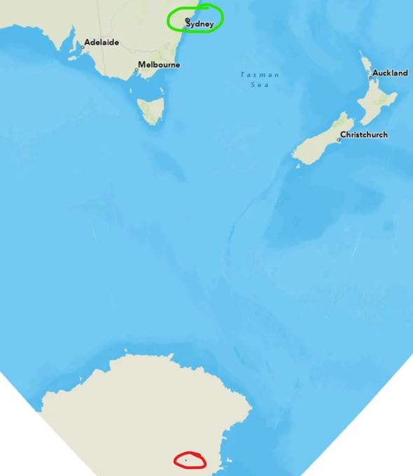
However, when I open the output DWG, most of the data is correctly reprojected (matching what I see in the Inspector) but some features remain in the original coordinate system, thus showing up in Antarctica:
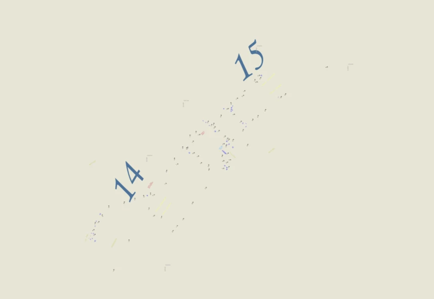
Zoomed in at the portion in Antarctica:
I've tried several troubleshooting steps:
- A simple read/write workbench
- Writing to DXF instead of DWG
- Using the RealDWG reader/writer
- Using default DWG reader settings (no customisation)
I saw this question is similar to mine, but I didn’t have any luck writing to dxf instead:
None of these things have fixed the issue. It seems to mostly affect text features, although some text is reprojected correctly, so I'm really not sure what is causing it! I haven’t been able to identify a consistent pattern or reason why certain features remain in the wrong CRS. I've also experienced this with a few CAD files now, so it's not limited to just this one.
Has anyone encountered this before or have suggestions on what might be causing it?