Question

Create a cube from a point

  • October 31, 2019
  • 7 replies
  • 122 views

philippeb
Enthusiast
Forum|alt.badge.img+22

I'm starting to create 3D modeling with FME and I can't find the way to create flat 3D surfaces from 2D geometry.

With the Bufferer everything is rounded. How can I create a cube from a point? Or a building from a squared polygon?

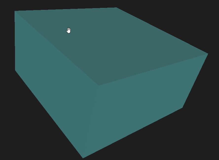
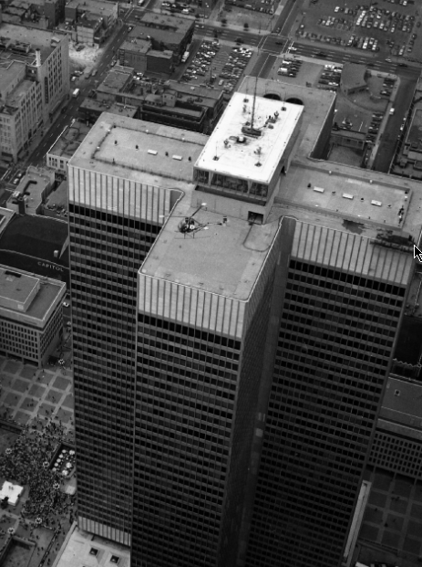
For example, how can I create this building from a 2D polygon?

Thanks

This post is closed to further activity.
It may be an old question, an answered question, an implemented idea, or a notification-only post.
Please check post dates before relying on any information in a question or answer.
For follow-up or related questions, please post a new question or idea.
If there is a genuine update to be made, please contact us and request that the post is reopened.

7 replies

jdh
Contributor
Forum|alt.badge.img+37
  • Contributor
  • 2002 replies
  • October 31, 2019

To go from a 2d footprint to a 3D building you would use the Extruder.


To go from a point to a rectangular footprint, I would use a 2DBoxReplacer and optionally Rotator.


The parameters of the twobox replacer would be something along the lines of


Min X: @XValue() - @Value(width)/2


Max X: @XValue() + @Value(width)/2


Min Y: @YValue() - @Value(length)/2


Max Y: @YValue() + @Value(length)/2

mark2atsafe
Safer
Forum|alt.badge.img+56
  • Safer
  • 2554 replies
  • October 31, 2019

You could also use the BoundingBoxReplacer on your buffer. That way you get a rectangular shape (no rounding). Then the Extruder.

Really there are a lot of ways you could do this. I don't see much of a difference in performance for any of them.


philippeb
Enthusiast
Forum|alt.badge.img+22
  • Author
  • Enthusiast
  • 329 replies
  • November 1, 2019

The Extruder is exactly what I was searching for.

I have a little problem though, when I add transparency to the solid.

This is a solid without transparency : Top notch.

When I add transparency (GeometryColorSetter, Alpha = 0.5), this is what my solid looks like.

The transparency function itself is doing a great job, but we can easily see those lines onto the surface.

Would that be possible to make those lines disappear when I add transparency?


mark2atsafe
Safer
Forum|alt.badge.img+56
  • Safer
  • 2554 replies
  • November 1, 2019

The Extruder is exactly what I was searching for.

I have a little problem though, when I add transparency to the solid.

This is a solid without transparency : Top notch.

When I add transparency (GeometryColorSetter, Alpha = 0.5), this is what my solid looks like.

The transparency function itself is doing a great job, but we can easily see those lines onto the surface.

Would that be possible to make those lines disappear when I add transparency?

What format are you writing to and what product is that you are viewing the data in? Technically speaking, extruding creates an IFMEExtrusion feature, which is an extruded face, and faces often get viewed with those lines (can't remember what they are called).

You could try using the SolidBuilder transformer to turn your extrusion into an IFMEBRepSolid geometry. Or try the CSGBuilder transformer to turn the feature into an IFMECSGSolid. Again, it depends on what format you are writing and what tool you are using to view the data, but the different geometry types might be treated differently.

To be honest, that's sort of a guess. But I know that 3D features can have subtly different geometry types. Not everything that looks like a block is actually "solid", and so it's reasonable to think they might get treated differently.


philippeb
Enthusiast
Forum|alt.badge.img+22
  • Author
  • Enthusiast
  • 329 replies
  • November 1, 2019

What format are you writing to and what product is that you are viewing the data in? Technically speaking, extruding creates an IFMEExtrusion feature, which is an extruded face, and faces often get viewed with those lines (can't remember what they are called).

You could try using the SolidBuilder transformer to turn your extrusion into an IFMEBRepSolid geometry. Or try the CSGBuilder transformer to turn the feature into an IFMECSGSolid. Again, it depends on what format you are writing and what tool you are using to view the data, but the different geometry types might be treated differently.

To be honest, that's sort of a guess. But I know that 3D features can have subtly different geometry types. Not everything that looks like a block is actually "solid", and so it's reasonable to think they might get treated differently.

OK great I'll try those suggestions and I'll get back to you.

My screen shots have been taken from the Data Inspector, I'm not writing in anything right now. Ultimately I would like to write this into a 3DPDF.

Have a great week end!


mark2atsafe
Safer
Forum|alt.badge.img+56
  • Safer
  • 2554 replies
  • November 1, 2019

OK great I'll try those suggestions and I'll get back to you.

My screen shots have been taken from the Data Inspector, I'm not writing in anything right now. Ultimately I would like to write this into a 3DPDF.

Have a great week end!


So that might just be an FME thing then, to show where those faces are. If you write to 3D PDF then Adobe might not show them the same way. Remember the Data Inspector is for validation more than visualization, so I wouldn't worry too much at this point. If you get the same issue in PDF then I can consult with the developers.


philippeb
Enthusiast
Forum|alt.badge.img+22
  • Author
  • Enthusiast
  • 329 replies
  • November 5, 2019

So that might just be an FME thing then, to show where those faces are. If you write to 3D PDF then Adobe might not show them the same way. Remember the Data Inspector is for validation more than visualization, so I wouldn't worry too much at this point. If you get the same issue in PDF then I can consult with the developers.

You are right, everything look fine into my PDF. Thanks a lot for your help!