
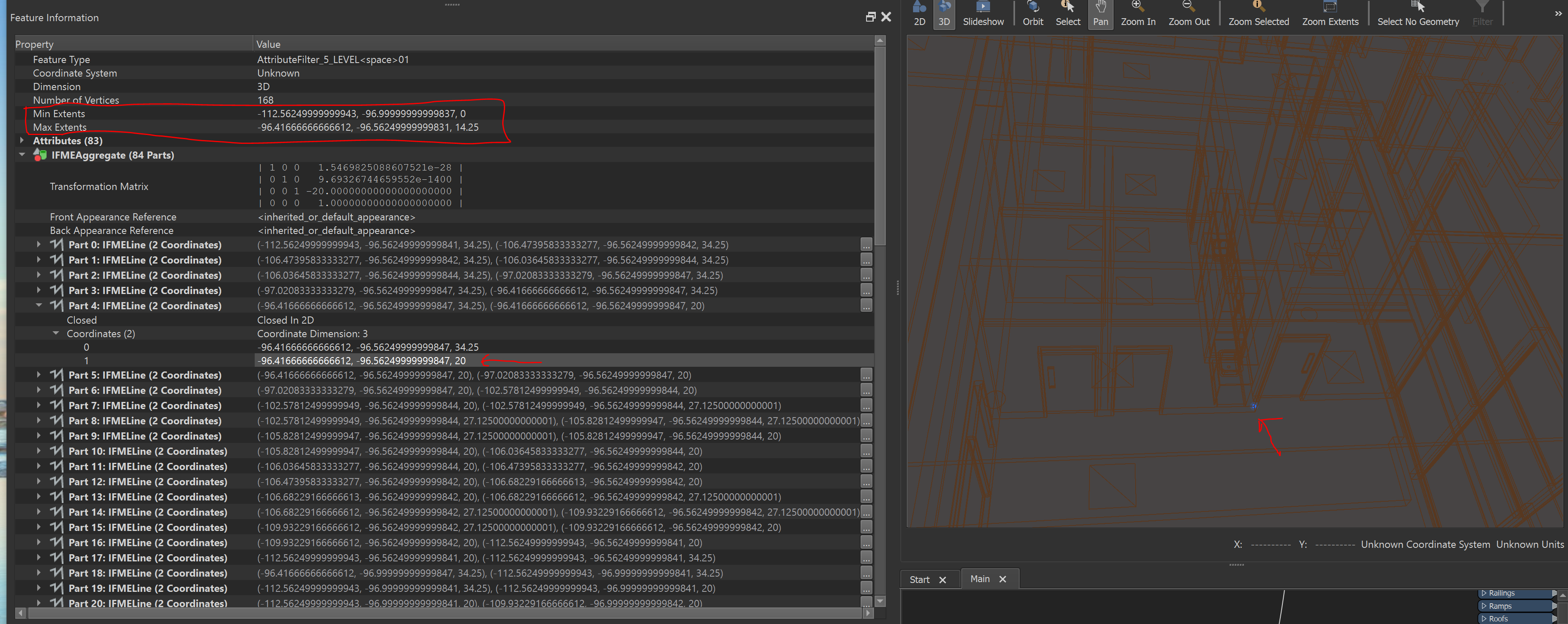
They have more in common with the Min and Max Extents in the Feature Information window than down below where the geometry coordinates are. Should I expect the indices to align with the existing coordinates? Do aggregates change how the CoordinateExtactor works? It is really mystifying. Any insight is appreciated.

Solved
CoordinateExtractor Questions: I am using the coordinate extractor on a large amount of 3D wireframe wall shape aggregates. When I look at the indices, not only are they not in the same order as the FME geometry, but they are completely differen
 +9
+9- Contributor
Best answer by itsmatt
I can't share the data as is because it is sensitive and the file is huge. I'll find a way to send a pared-down version. What I am trying to understand is why the extracted coordinates are completely different than the FME geometry coordinates that it is supposed to extract. It seems like the coordinate extractor is looking at the wrong data. Sorry it's hard to explain. I was hoping the files I sent would show that difference.
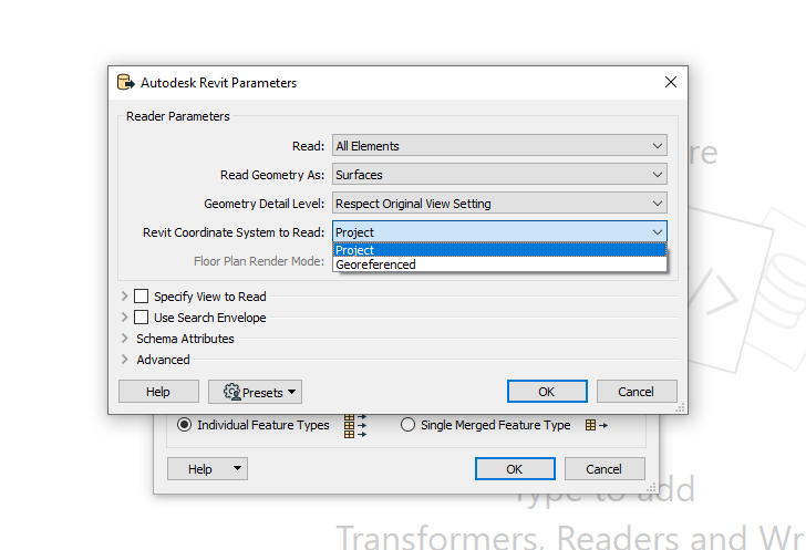
Here is another screenshot taken from the Revit Reader. Maybe it's a Revit Reader issue? Notice the min/max extents have nothing to do with the geometry coordinates. It seems to have ignored the floor height:
So when reading from Revit there are two options to choose as to where the geometries should be relative to.
 I think the issue here is that the Geometry you see in the Feature Information window is not the real geometry - the extracted coordinate and bounds reflect the real geometry.
Storing geometry with a transformation matrix can be faster than applying the transformation to the coordinates. For example, when in Revit and you model something, if you copy and paste a group of objects instead of calculating all the coordinates, Revit might be choosing instead to just track the movements you make of the objects.
If you want to apply the transformation matricies to the data (get rid of them) you can reproject the data and then reproject it back.
This post is closed to further activity.
It may be an old question, an answered question, an implemented idea, or a notification-only post.
Please check post dates before relying on any information in a question or answer.
For follow-up or related questions, please post a new question or idea.
If there is a genuine update to be made, please contact us and request that the post is reopened.


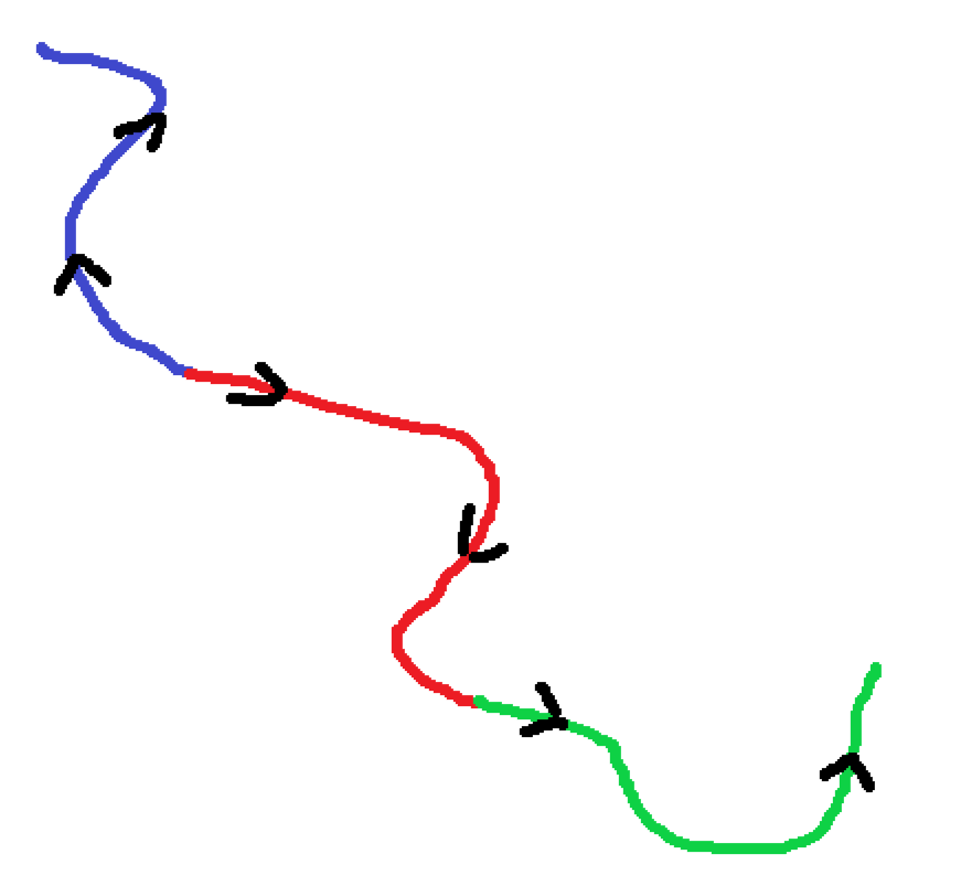 These lines are all topologically valid (each line that touches shares the same vertex). Notice how the blue line is drawn in a different direction to the red and the green.
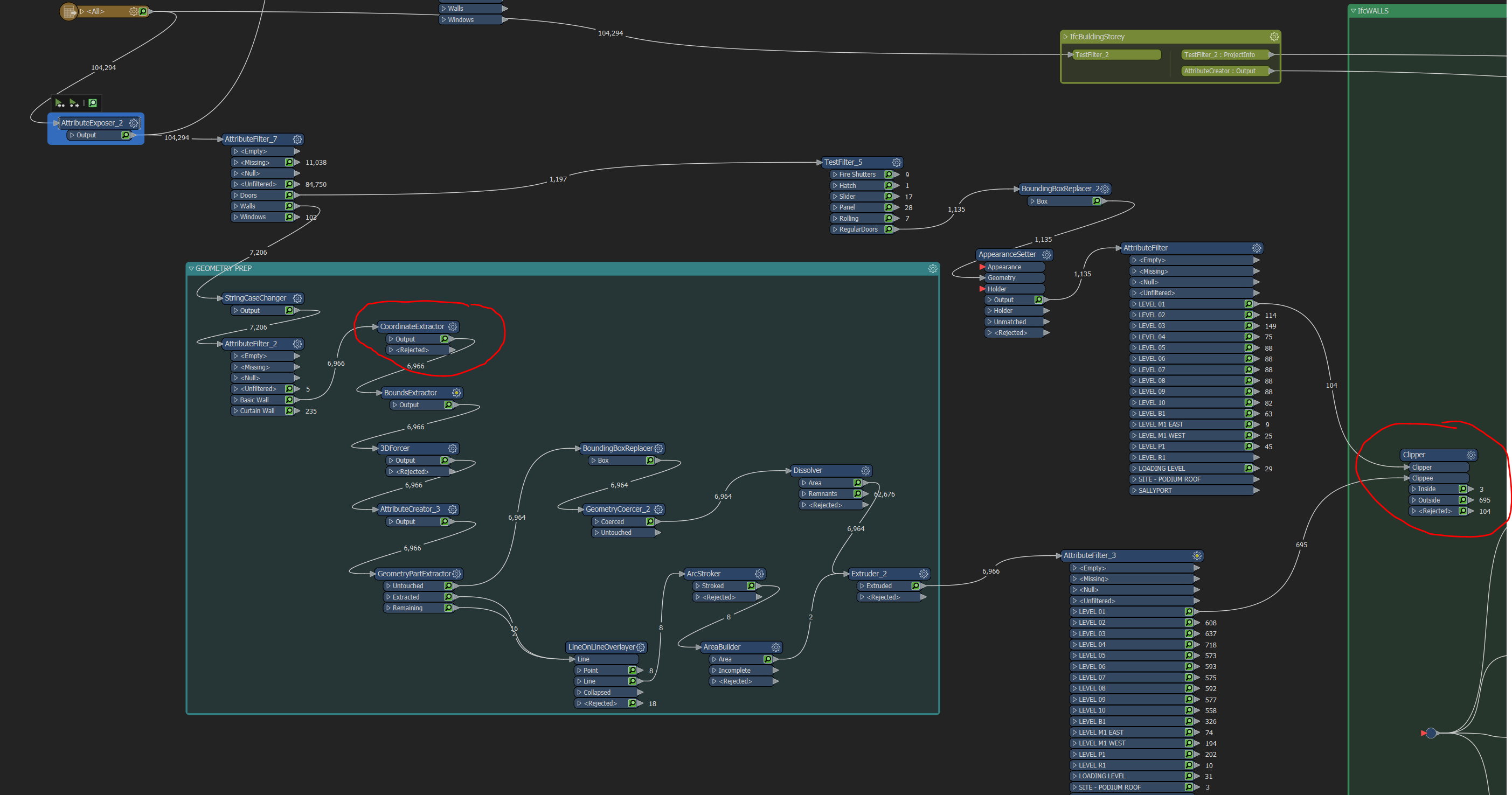 The red circles are where I got the Feature info and the output for visual preview, respectively.
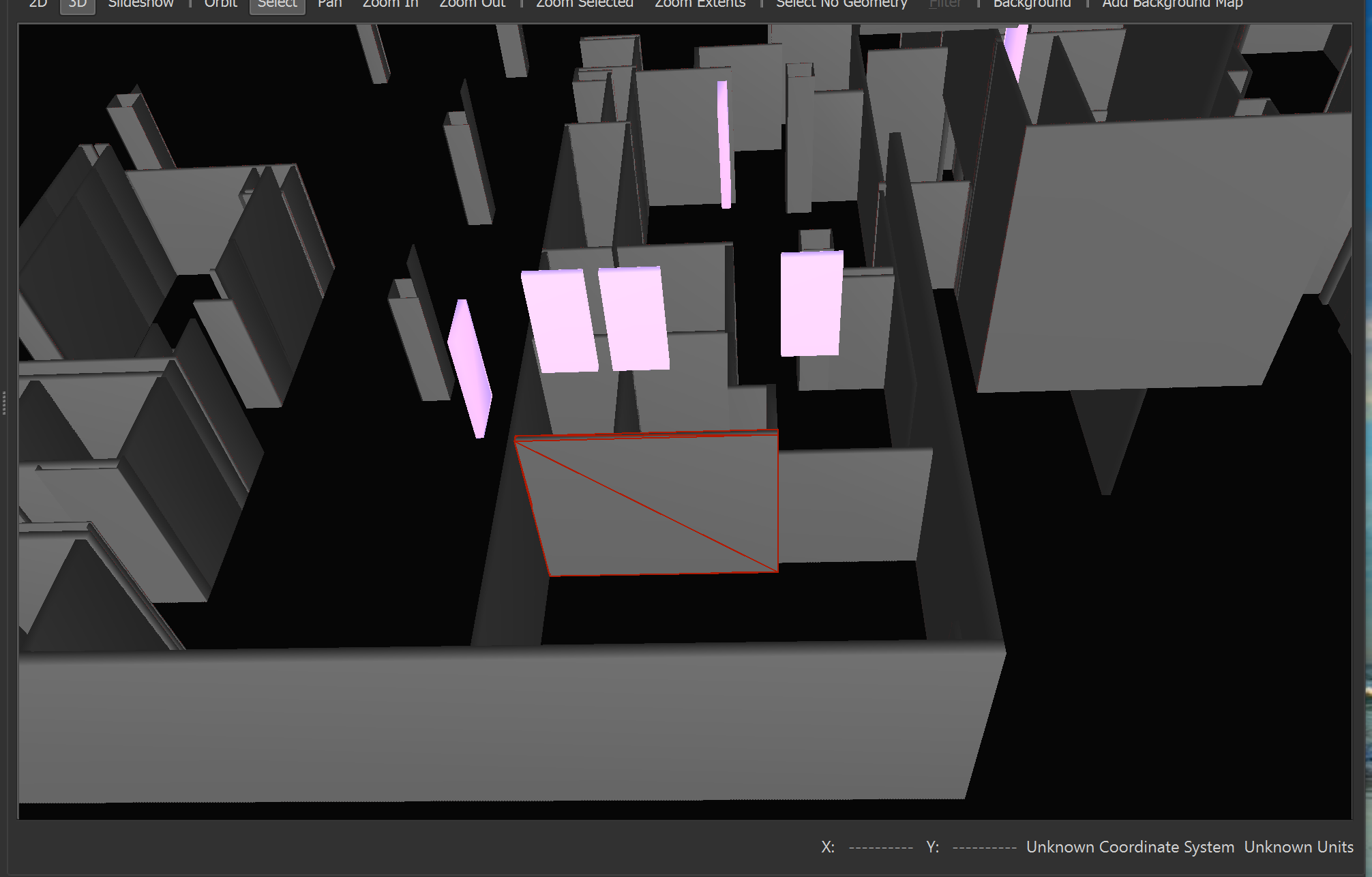 The selected wall is the feature in the attachments, only flattened and extruded using the bounds as a base. _zmax -_zmin = Extrusion distance.


Login to the community
No account yet? Create an account
An FME Account is required to contribute
LoginEnter your E-mail address. We'll send you an e-mail with instructions to reset your password.