Hi @mlupien,
The AffineWarper transformer can help you out with the alignment. It will calculate an affine transformation (combination of offset, rotation and scale) to align the original DWG data with the Mapinfo base map. To use the transformer, please follow these steps:
Examine both datasets in the FME Data Inspector, and find at least four common points between the two datasets.
Enter the coordinates of these common points into Excel, or other spreadsheet app, with one point per row, in the order DWG_X, DWG_Y, Mapinfo_X, Mapinfo_Y. Save as a CSV file.
Create a new DWG to DWG workspace, with Dynamic Schema set in the Generate dialog. Set Explode Blocks to No in the Reader Parameters. Set the writer template file to be the source DWG file. This should produce a very simple workspace, with a single input and output feature type.
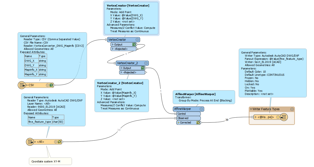
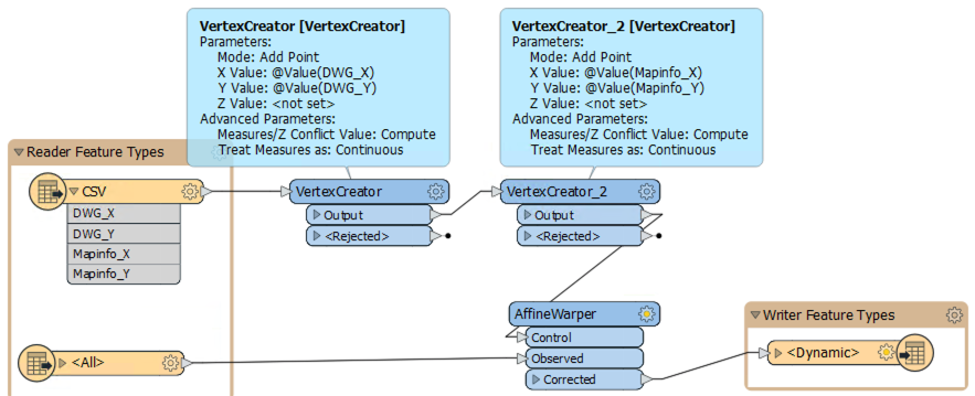
Add a CSV reader to the workspace, using the CSV file you created of the common points. Connect this to a VertexCreator to create a point form the DWG X and Y values. Add a second VertexCreator to add a point from the Mapinfo X and Y values. These will be your control vectors.
Connect the output from the second VertexCreator to the Control port of an Affine Warper. Connect the source DWG feature type to the Observed port, and the destination DWG feature type to the output Corrected port.


")