Question

Close polyline


hy...at the begininng sorry on my bed english...


i have a dataset of 3d polylines witch representing buildings...someone are closet,


someone are not...my problem is how to close unlose polyline...


i use coordinate extractor to extract first and last point of the polyline, and than test where is first coordinate is the same like last, that is closet polyline and thats ok.


than, i find the neigbour of uncloset polyline (because i want to line of closet polyline assign unclose polyline) and thats works fine.


and here is the problem..how to close unclosed polyline with line of closed polyline


but that interpolates z value between points of not closed lines.?? i hope you undestand what i am trying to do


16 replies

  • Author
  • December 12, 2013

  • Author
  • December 12, 2013
http://www.filedropper.com/pic_1


http://www.filedropper.com/fme


here is workbench and example in microstation....so, green line is unclosed, and red line is the line with i need to closed that green line..and red line need to be on z value between first and last point of green line..

gio
Contributor
Forum|alt.badge.img+15
  • Contributor
  • December 12, 2013
u could project the lines to the x,y plane goin 2D (as in the view of your pic i assume).


In 2D


If u dont have it already, make a ID for the polylines in 2 classes.


Intersect the lines then build areas.Discard unused lines.


Line on area overlayer with the original redlines to get the used pieces.


Get start and endnodes of those and then use x,y to get the x,y,z of the greenlines in 3D.


Then connect those. Then connect these with gree lines.

  • Author
  • December 12, 2013
http://www.filedropper.com/example


can you help me with this workbench?

takashi
Influencer
  • December 12, 2013
Hi,


I guess you need to set Z-value of start / end node of the Green line; the z-value should be interpolated based on both end nodes (x, y, z) of related Red line segment. If so, the following way could be available. See images and related help documentations to configure detailed parameter settings for the transformers.   S1. Create Vertex Points of Green Line 1) Counter appends unique identifier (ID) to every line. 2) CoordinateCounter gets the number of vertices (_coordcount) of each line. 3) Chopper transforms lines to every vertex points. Mode: By Vertex Meximum Vertices: 1 4) Counter_2 appends sequential number (_count) to every point. Counter Name: @Value(ID) Count Start: 1


5) Tester divides points into start / end nodes and others. If 1 < _count AND _count < _coordcount --> PASSED (others) Else --> FAILED (start / end nodes) 
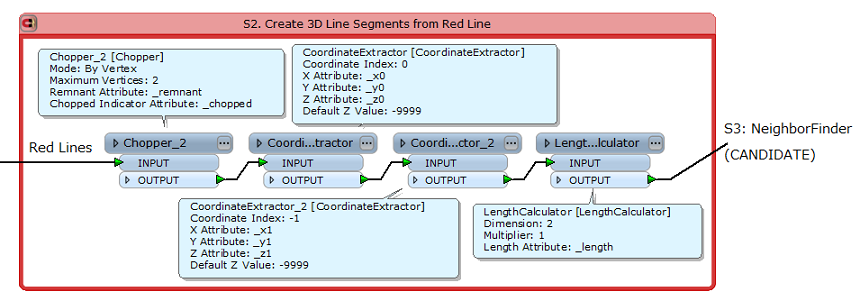
S2. Create 3D Line Segments from Red Line 1) Chopper_2 transforms each polyline to individual line segments. Mode: By Vertex Meximum Vertices: 2 2) CoordinateExtractor extracts start coordinate (_x0, _y0, _z0). 3) CoordinateExtractor_2 extracts end coodinate (_x1, _y1, _z1). 4) LengthCalculator calculates 2D lenght of the line segment (_length).


S3. Calculate and Set Z-Value to Start / End Node of Green Line 1) NeighborFinder finds location on the Red line segment closest to each start / end node of Green line. 2) AttributeCreator calculates these values. _dx = _closest_candidate_x - _x0 _dy = _closest_candidate_y - _y0 _dz = _z1 - _z0 3) 3DForcer calculates and sets Z to start / end node of Green line. Z(Elevation) = _z0 + _dz * sqrt(_dx * _dx + _dy * _dy) / _length


  S4. Re-create Green Line and Close 1) Sorter sorts vertex points by ID and _count. 2) PointConnector connects vetex points to re-create Green lines. 3) LineCloser close the lines.


Hope this helps.


Takashi

  • Author
  • December 12, 2013
tnx, but i think that are not giving me the right result...


here is picture what i realy want..


on the left picture is current situation, green letter are heigh of first and last point of green line, and red one is of the red line (but red line is not split on the intersect, and should be. text 15 is universal, is not the same on one line, is variable.)..on the right picture is what i need...red line shoud be cliped, snaped to green line so that could be generated polygon, and the height of that line shoud be interpolated...

  • Author
  • December 12, 2013
http://www.filedropper.com/example_1


here is the link...sorry

takashi
Influencer
  • December 13, 2013
Sorry. I didn't understand your question exactly. This workspace example might help you. Please download and evaluate it.  http://www.pragmatica.jp/fmepedia/131213WorkspaceExample.zip

  • Author
  • December 13, 2013
tnx...i think that could help...can you just save that workspace in version 2011 or 2012 because i can't see everything..tnx

takashi
Influencer
  • December 13, 2013
I'm using FME 2013.


Both 2011 and 2012 are also installed in my machine, but I used some new functionalities of 2013 in the workspace example, so cannot save it for old version simply. Just a moment.

takashi
Influencer
  • December 13, 2013
Created this workspace example using FME 2012 SP4 Build 12266.


http://www.pragmatica.jp/fmepedia/131213WorkspaceExample_2012SP4.zip


Hope this helps.


Takashi


  • Author
  • December 13, 2013
thanks, that looks impressive..


but i don't know why FME stoped on Feature Merger, from output port complete does not derive anything...i attach you original dgn file, and if you have time please check what is going on..i really dont know


http://www.filedropper.com/example_2

takashi
Influencer
  • December 13, 2013
Found 2 issues. 1. All the riginal red lines (6) are not polylines. Those are individual line segments. Try using the LineJoiner transformer after reading. 2. Connect the Chopper_2 UNTOUCHED port and the LengthCalculator_2 INPUT port. It's my mistake. UNTOUCHED port of the Chopper has been removed in FME 2013, I forgot it.

  • Author
  • December 13, 2013
it's better tnx, but still i can't get all polygon...i get 83 polygon, and still have ten - fifteen witch is not created when i overlay with input dataset.

takashi
Influencer
  • December 15, 2013
There are some exceptional conditions in the data. e.g. small gap between end of green line and red line, ring-shaped red lines. I think you will have to inspect data in detail and consider appropriate pre-processing or other approaches corresponding to actual conditions.

  • Author
  • December 16, 2013
i found two more example which should be included in FME.


First, when i look in atribute of executed polygons, i see that the first and last point of polygon dosen't have the same heigh, e.g. polygon on picture 1 is for the first point take the height of the red line, and the last point of the green but they should be the same. And FME execute only one polygon,


probably because it is identical green line that connects them. There is another problem continues.


One red polygon is divided by more green lines (picture 2). here should be five polygons. one green line is identical for two polygons. FME does not create none polygon. do you have any idea? tnx


http://www.filedropper.com/pic1


http://www.filedropper.com/pic2


Cookie policy

We use cookies to enhance and personalize your experience. If you accept you agree to our full cookie policy. Learn more about our cookies.

 
Cookie settings