Question

How to convert Cad points to geodb_polylines?

  • March 28, 2014
  • 8 replies
  • 36 views

Forum|alt.badge.img
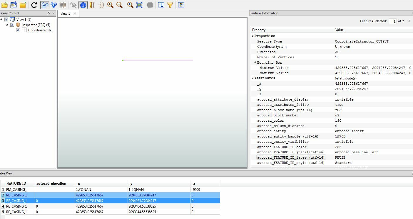
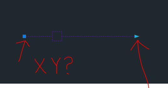
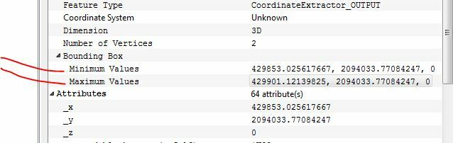
I have a series of dynamic blocks that can stretch in AutoCAD that I would like to convert and store in a geodb_polyline feature set., is this possible?  I tried Point connector with no luck?
This post is closed to further activity.
It may be an old question, an answered question, an implemented idea, or a notification-only post.
Please check post dates before relying on any information in a question or answer.
For follow-up or related questions, please post a new question or idea.
If there is a genuine update to be made, please contact us and request that the post is reopened.

8 replies

takashi
Celebrity
  • March 29, 2014
Hi,


Whether it's possible depends on the condition.


The PointConnector is usually used to transform a series of points into a line. Why didn't it work in your case?


If the reason had been clarified, maybe we could suggest a solution.


Takashi

gio
Contributor
Forum|alt.badge.img+15
  • Contributor
  • March 31, 2014
To use pointconnector, the points must be ordered (using some ID).


I assume the blocks are points? Or are we talking insertionpoints?


Maybe example data, pics or, as Takashi says, some clarification?


Gio


Forum|alt.badge.img
  • Author
  • April 2, 2014
Thank you for your help and comments. I think that the pointconnector will not work due to the dynamic block only has one point, but in AutoCAD it appears as a polyline. Is there a way to do the Pointconnector for the start and end XY?

Forum|alt.badge.img
  • Author
  • April 2, 2014


Forum|alt.badge.img
  • Author
  • April 2, 2014


I would have to use these atributes to create the line.

takashi
Celebrity
  • April 2, 2014
I guess you have extracted required coordinates (x, y, z). Then, how about creating point based on the coordinate before connecting points?


To create a point, you can use the VertexCreator (Mode: Replace with Point).


If you are using FME 2013, use 2D or 3DPointReplacer instead.

gio
Contributor
Forum|alt.badge.img+15
  • Contributor
  • April 2, 2014
Hi,


A block itself only has, indeed, an insertion point.W


When u insert the block(s) in a drawing, ie an empty drawing, you can then read it.


Exposing relevant autocad attribute gives u acces to the data, like start and end point.


I have done this to legend-blocks we use in autocad. By inserting it, i could completly read it, geometry, values, text, logo's, using fme.


Gio


gio
Contributor
Forum|alt.badge.img+15
  • Contributor
  • April 2, 2014
I just checked the workspace i used, i appeared to have read the PSVPORTS, the paperspace.


In an epty dwg where bound the relevant block.


That way i got acces to the block-content using fme, normal autocad reader.


Gio