Question

DWG BIM to GIS


Hi,

I want some help in the right direction with converting a DWG BIM 3D file to a DWG 3D CAD/GIS format.

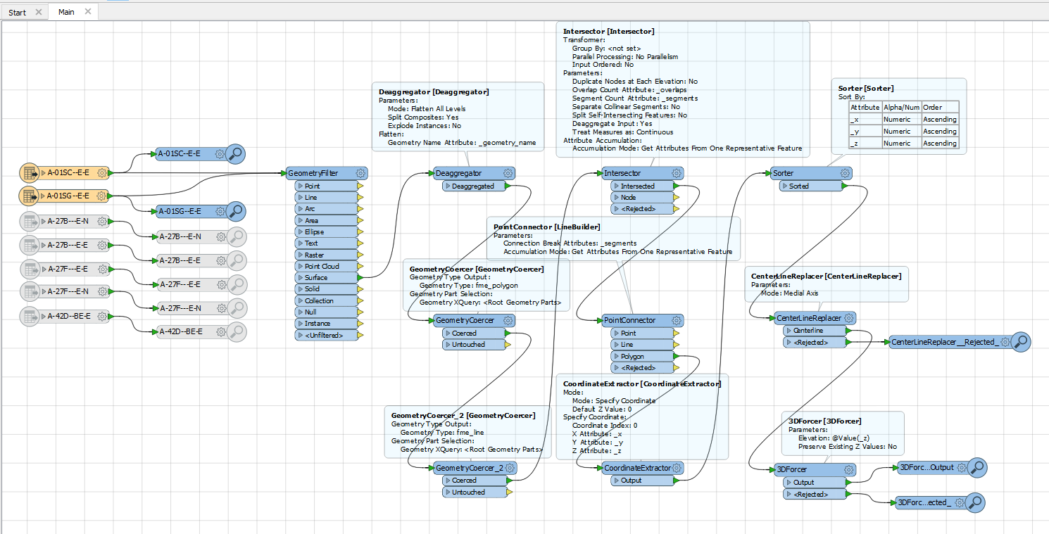
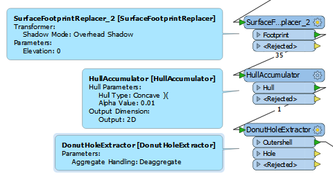
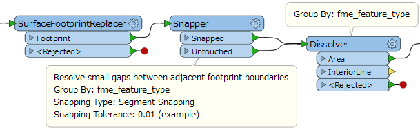
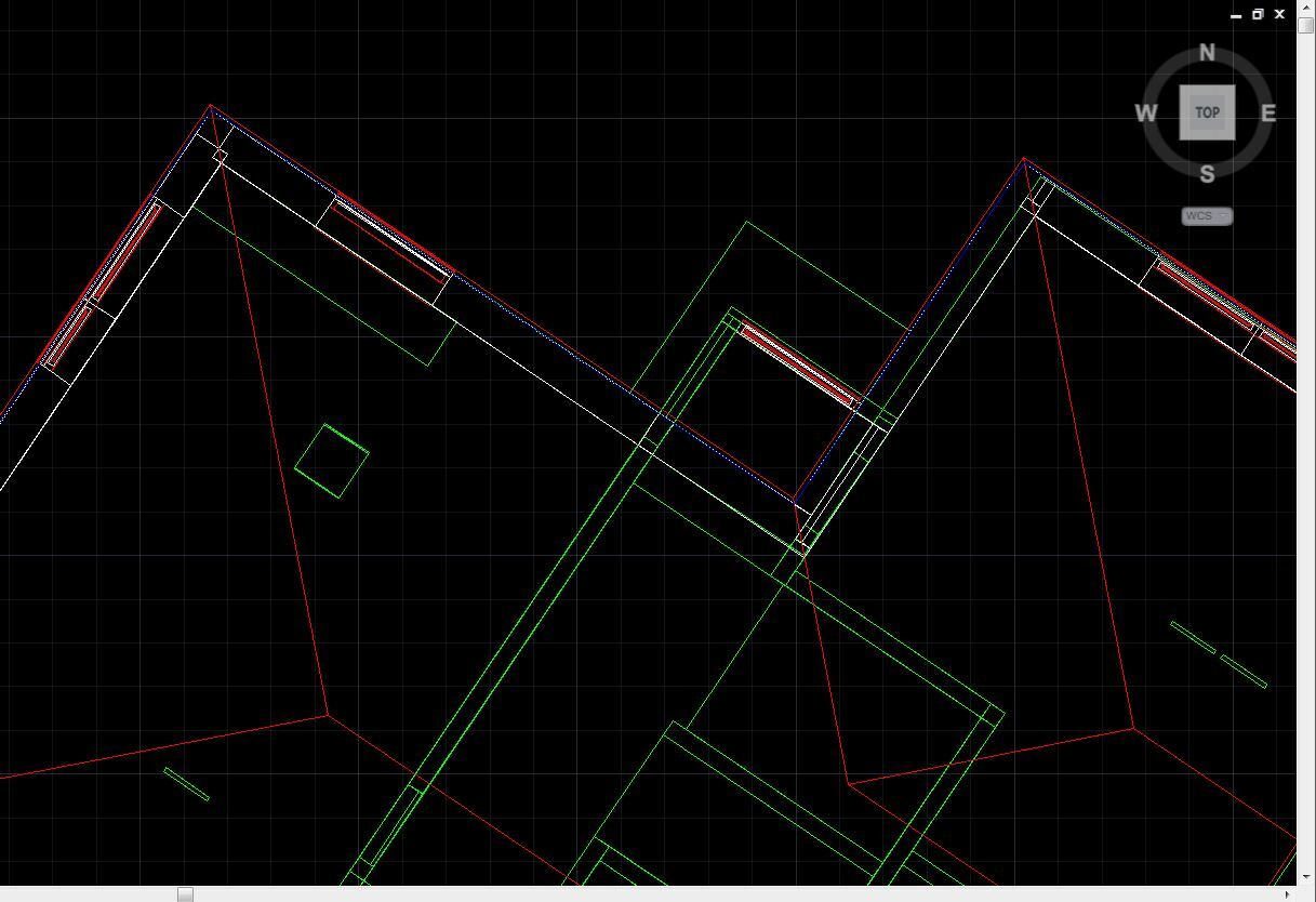
I cannot figure out how to simpoify the 3D-model so that only the outer lines of the 3D model remains

.

I want it to look like the blue line in the attached picture.

Best Regards,

Jonas

7 replies

  • Author
  • March 28, 2017

Hi again,


Here is the code that I figured out so far.


But the lines is in the middle and not outside and it is very slow! It takes many days if I run with all the object as input...


Please help!


Best regards,


Jonas


bim-2-cad-5.fmw 


  • Author
  • March 28, 2017
Heres the FME-code...


/Jonas


mygis
Contributor
Forum|alt.badge.img+12
  • Contributor
  • June 27, 2017
Hi @bigjonas69 ,


Is you workspace doing the process up to your expectations?


lars_de_vries
Forum|alt.badge.img+10

Hi @bigjonas69,

If I understand your question correctly, the solution might be much simpler. When you place a combination of a SurfaceFootprintReplacer, a HullAccumulator and a DonutHoleExtractor after the GeometryFilter, you'll get exactly a polygon that represents the blue line in your first screendump.

I have set the HullAccumulator to "Hull Type: Concave )(" and "Alpha Value: 0.01". This will take some time, but delivers the output you desire. Also you should set the Group By to fme_feature_type if you want to distinct between the two DWG layers that are enabled in your workspace.

If you do not want a polygon, but a polyline, you could use a GeometryCoercer to do so.


takashi
Contributor
Forum|alt.badge.img+19
  • Contributor
  • September 16, 2017

Hi @bigjonas69, I think you can use the Dissolver to merge footprint polygons for each layer. However, depending on the data condition (slight gaps within a tolerance), a preprocess to perform snapping segments could be required.

In addition, after the Dissolver, additional transformers such as Generalizer (Douglas algorithm) and SpikeRemover might be helpful to clean the geometries.


  • Author
  • September 16, 2017
lars_de_vries wrote:

Hi @bigjonas69,

If I understand your question correctly, the solution might be much simpler. When you place a combination of a SurfaceFootprintReplacer, a HullAccumulator and a DonutHoleExtractor after the GeometryFilter, you'll get exactly a polygon that represents the blue line in your first screendump.

I have set the HullAccumulator to "Hull Type: Concave )(" and "Alpha Value: 0.01". This will take some time, but delivers the output you desire. Also you should set the Group By to fme_feature_type if you want to distinct between the two DWG layers that are enabled in your workspace.

If you do not want a polygon, but a polyline, you could use a GeometryCoercer to do so.

It worked after I only took one layer.


Group by have also worked.


Thanks!


Sincerely,


Jonas


  • Author
  • September 16, 2017
takashi wrote:

Hi @bigjonas69, I think you can use the Dissolver to merge footprint polygons for each layer. However, depending on the data condition (slight gaps within a tolerance), a preprocess to perform snapping segments could be required.

In addition, after the Dissolver, additional transformers such as Generalizer (Douglas algorithm) and SpikeRemover might be helpful to clean the geometries.

Okay, thank you for the tips and trix...


Sincerely,


Jonas


Cookie policy

We use cookies to enhance and personalize your experience. If you accept you agree to our full cookie policy. Learn more about our cookies.

 
Cookie settings