Question

How to move node with connected edges?

  • November 30, 2017
  • 6 replies
  • 16 views

Forum|alt.badge.img

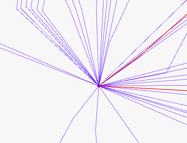
I build two topologies (used TopologyBilder) which have nodes on the same coordinate (red and blue nodes on the picture). Now I would like somehow "move" (or offset) one of the nodes. The problem is, the endpoints of the connected edges should follow the node. How can I solve this problem?

6 replies

takashi
Influencer
  • November 30, 2017

Hi @nindalf, I think you can use the VertexCreator (Mode: Replace Point At Index) here. The index 0 indicates the first vertex, -1 indicates the last vertex.


jdh
Contributor
Forum|alt.badge.img+28
  • Contributor
  • November 30, 2017

If I understand correctly, you only want to move one colour node and it's corresponding lines? Assuming you have someway of isolating the two topologies, you could offset the node then send it to the Anchor port of the AnchoredSnapper, with the lines sent to the Candidate port, with mode End Point Snapping


Forum|alt.badge.img
  • Author
  • November 30, 2017
jdh wrote:

If I understand correctly, you only want to move one colour node and it's corresponding lines? Assuming you have someway of isolating the two topologies, you could offset the node then send it to the Anchor port of the AnchoredSnapper, with the lines sent to the Candidate port, with mode End Point Snapping

Ok, this sounds interesting. Actually the two topologies are already separate. I will try this and let you know if it worked. Is there a possibility in FME to offset a node, snap the lines and repeat this step as long as I have nodes in a queue? If I offset all nodes at once and snap the lines afterwards I could produce errors.


Forum|alt.badge.img
  • Author
  • November 30, 2017
takashi wrote:

Hi @nindalf, I think you can use the VertexCreator (Mode: Replace Point At Index) here. The index 0 indicates the first vertex, -1 indicates the last vertex.

This is probably a possibility but the problem is I need to know on which vertex of the line the node is connected (index 0 or -1). This seems to be hard to detect...


fmelizard
Safer
Forum|alt.badge.img+18
  • Safer
  • November 30, 2017

Hi @nindalf Use a TopologyBuilder to see which lines are connected to the node


Forum|alt.badge.img
  • Author
  • December 4, 2017

Ok, I've found a solution for the problem. The solution looks as follow:

TS are the nodes which I like to separate; MS = medium voltage (red lines); NS = low voltage (blue lines). The result of this block is just the red topology with the offset nodes.

Here is the result to prove it's working:

Thank's for your help!


Cookie policy

We use cookies to enhance and personalize your experience. If you accept you agree to our full cookie policy. Learn more about our cookies.

 
Cookie settings